Manual 35018V1 505XT Digital Control System for Steam Turbines
Woodward 197
Table 6-1. ASCII vs RTU Modbus
Characteristic ASCII RTU
Coding System Hexadecimal (uses
ASCII printable binary
characters: 0-9, A-F)
8-bit binary
Start Bits 1 1
Data Bits per Character 7 8
Parity Even, odd, or none Even, odd, or none
Stop Bits 1, 1.5, or 2 1, 1.5, or 2
Baud Rate 110, 300, 600, 1200,
1800, 2400, 4800, 9600,
19200, 38400, or 57600
110,300, 600, 1200,
1800, 2400, 4800, 9600,
19200, 38400, or 57600
Error Checking LRC (Longitudinal
Redundancy Check)
CRC (Cyclical
Redundancy Check)
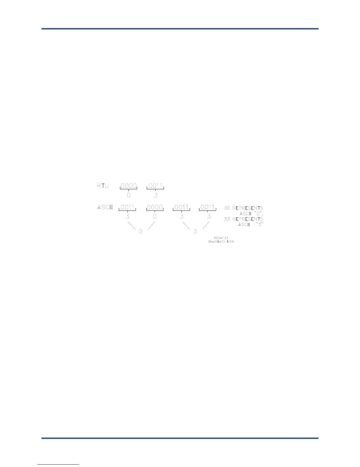
In the RTU mode, data is sent in 8-bit binary characters and transmitted in a continuous stream. In the
ASCII mode, each binary character is divided into two 4-bit parts (high order and low order), changed to
be represented by a hexadecimal equivalent, then transmitted, with breaks of up to 1 second possible.
Because of these differences, data transmission with the ASCII mode is typically slower (see Figure 6-1
below).
Figure 6-1. ASCII/RTU Representation of 3
The Modbus protocol allows one master and up to 247 slaves on a common network. Each slave is
assigned a fixed, unique device address in the range of 1 to 247. With the Modbus protocol, only the
network master can initiate a transaction. A transaction consists of a request from the master to a slave
unit and the slave’s response. The protocol and Modbus device number are set in the Configuration mode
and can be adjusted in the Service Mode, if required.
The 505XT control is programmed to function as a slave unit only. As a slave unit, the 505XT will only
respond to a transaction request by a master device. The 505 can directly communicate with a DCS or other
Modbus supporting device on a single communications link, or through a multi-dropped network. If multi-
dropping is used, up to 246 devices (505s or other customer devices) can be connected to one Master
device on a single network. The control address is programmed under the 505’s communications block and
can be changed in the service mode, if needed.
Each message to or from a master has a defined structure called the message “frame”. A frame consists
of the slave device address, a code defining the requested data, and error checking information. See
Table 6-2.
 Loading...