SERVICING AND SPARES
6 720 803 599 (2012/06) 43
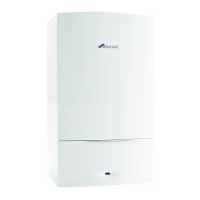
3. Remove air/gas manifold (I)
Fig. 63 Air/gas manifold
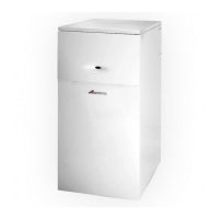
4. Open air/gas manifold (I).
B Carefully withdraw diaphragm (J) from fan intake tube and check for
soiling and splits.
Fig. 64 Diaphragm
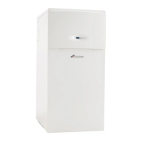
15. BURNER
B Remove the burner (H).
B Replace new burner in correct position.
B Ensure that a new seal (K) is used, refer to fig. 64.
Fig. 65 Burner removal
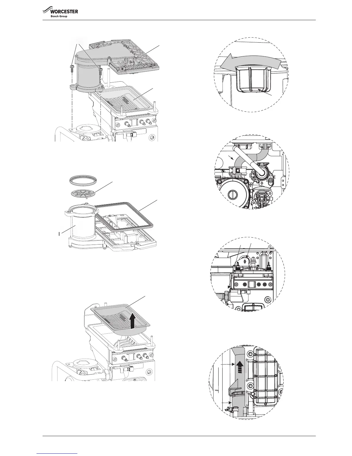
16. HEAT EXCHANGER
B Isolate flow and return valves and drain the boiler.
B Remove condensate trap (see page 41).
B Remove fan assembly (see page 42).
1. Remove plastic nut (A) from the base of the inner casing
Fig. 66 Heat exchanger removal 1
2. Remove return pipe at the bottom of heat exchanger.
Fig. 67 Heat exchanger removal 2
3. Remove screw at the top of the heat exchanger (C).
B Unscrew the flow pipe (D).
Fig. 68 Heat exchanger removal 3
4. Undo flue connection (E) from sump (F).
B Pull flue pipe up.
B Remove the heat exchanger.
Fig. 69 Heat exchanger removal 4
H
G
EE
3.
6720647361-65.1Wo
J
I
K
 Loading...