Installation
6720813174 (2014/09) 5
5Installation
5.1 General installation instructions
▶ Connect all pipes without forcing them into place.
▶ Make sure that the connections are tight and carry out a gas and
water tightness test after completing the connection work ( boiler
installation and servicing instructions).
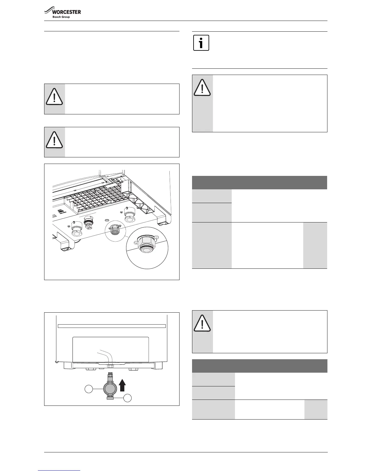
5.2 Making the gas connection
Fig. 3 Rubber seal
▶ Install the gas valve [1] onto the gas pipe (GAS) in the boiler.
▶ Connect the main gas supply to the gas isolating valve [2] free of
strain.
Fig. 4 Making the gas connection
[1] Gas isolating valve
[2] Gas connection
5.3 Removing the non-return valve (if necessary)
If the system pressure is not sufficient according to table 4, page 7, you
can remove the integrated non-return valve from single-boiler systems.
Selecting the correct pump group
▶ Select the correct pump group using table 4.
DANGER: Danger of fatal accident from explosive
fumes.
▶ Only carry out work on gas pipes and fittings if you
are properly certified (e.g. Gas Safe registered).
DANGER: Danger of fatal accident due to gas escaping.
▶ Make sure that the factory-fitted flat rubber seal is
located in the threaded connection (boiler side)
( fig. 3, detailed picture).
We advise you to integrate a gas filter in the gas line.
▶ Make the gas connection according to the country-
specific standards and regulations.
▶ Carry out gas leak test on gas connection using leak
detection spray
WARNING: Danger of fatal accident from explosive
fumes.
Pipes and screw connections may leak after
commissioning and maintenance activities have been
carried out.
▶ Carry out a leakage test.
▶ Only use approved detection products to locate
leaks.
GB162-
50
GB162-
65
GB162-
80
GB162-
100
Multi-boiler system
(cascade system)
UPER 25-80/UPS 25-80
pump group with pump
Single-boiler
system with
diverter valve
Single-boiler
system without
diverter valve
UPER 25-80/UPS 25-
80 pump group with
pump
1)
UPER
25-80/
UPS 25-80
pump
group with
pump
1) Only remove the non-return valve from the pump group (beneath the pump)
when installing single-boiler systems
2)
2) Do not use a pump group or switch, but select a separate pump using the
installation and servicing instructions with the boiler.
Table 2 Selecting the correct pump group
WARNING: Damage tot the unit in cascade systems or in
single-boiler systems with a switch due to the heating
medium flowing back.
▶ Only remove the non-return valve from the pump
group of a single-boiler system if the residual head
( table 4, page 7) is not sufficient.
GB162-
50
GB162-
65
GB162-
80
GB162-
100
Multi-boiler system
(cascade system)
not allowed
Single-boiler system
with diverter valve
Single-boiler system
without diverter
valve
Check the residual head
not
effective,
use pump
Table 3 Removing the non-return valve
 Loading...


