Installation
6720813174 (2014/09)6
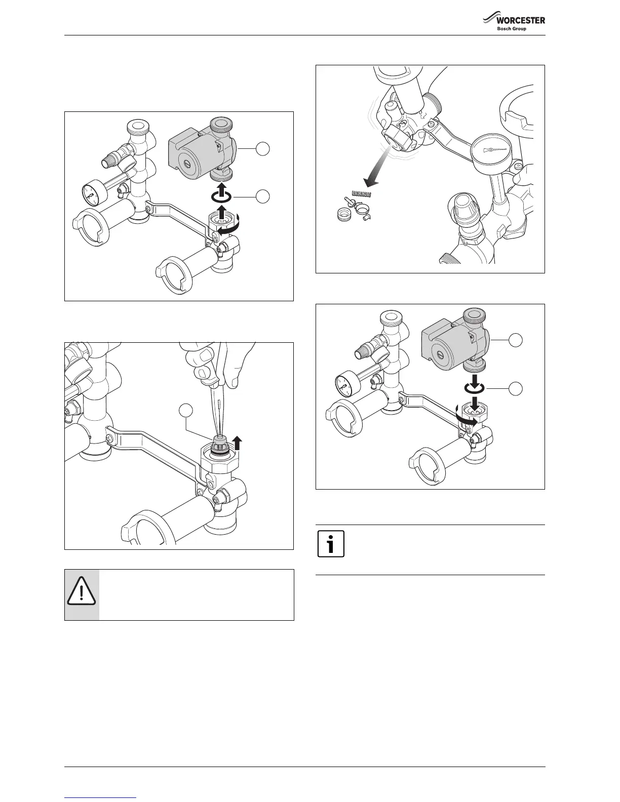
Removing the non-return valve
Remove the non-return valve before installing the heating flow and
return circuits otherwise it cannot be fully removed anymore!
▶ Remove the pump [1].
▶ Remove the flat rubber seal [2].
Fig. 5 Removing the pump
▶ Remove the non-return valve [1]. This will damage the non-return
valve beyond repair.
Fig. 6 Removing the non-return valve
▶ Rotate and shake the pump group.
Fig. 7 Removing the rest of the non-return valve
▶ Then fit back the flat rubber seal [2] and the pump [1].
Fig. 8 Fitting the pump
5.4 Installing the heating flow and return
▶ Install the blue and red isolating valve [2 and 6] with the flat rubber
seals in place on the CHR and CHF (boiler return and flow)
connections.
▶ Connect the flow pipe to the red isolating valve [3] free of strain. If
necessary, use the screw fitting (accessory, [4]).
▶ Connect the return pipe to the blue isolating valve [7] free of strain.
If necessary, use the screw fitting (accessory, [4]).
▶ Calculate the flow and return pipe diameters taking into
consideration the residual head downstream of the pump group with
the minimum required volume flow ( table 4, fig. 24 and fig. 25 on
page 11). The minimum diameters of the flow and return pipes are
1½’’ and Ø 35 mm.
WARNING: Damage to the unit due to reduced flow or
pipes becoming clogged up.
▶ Make sure that no fragments of the non-return valve
stay behind in the pipe.
To prevent pollution in the heating system we advise you
to integrate a dirt filter in the return circuit. When
connecting the heating boiler to an existing heating
system, this dirt filter must be installed.
 Loading...


