22
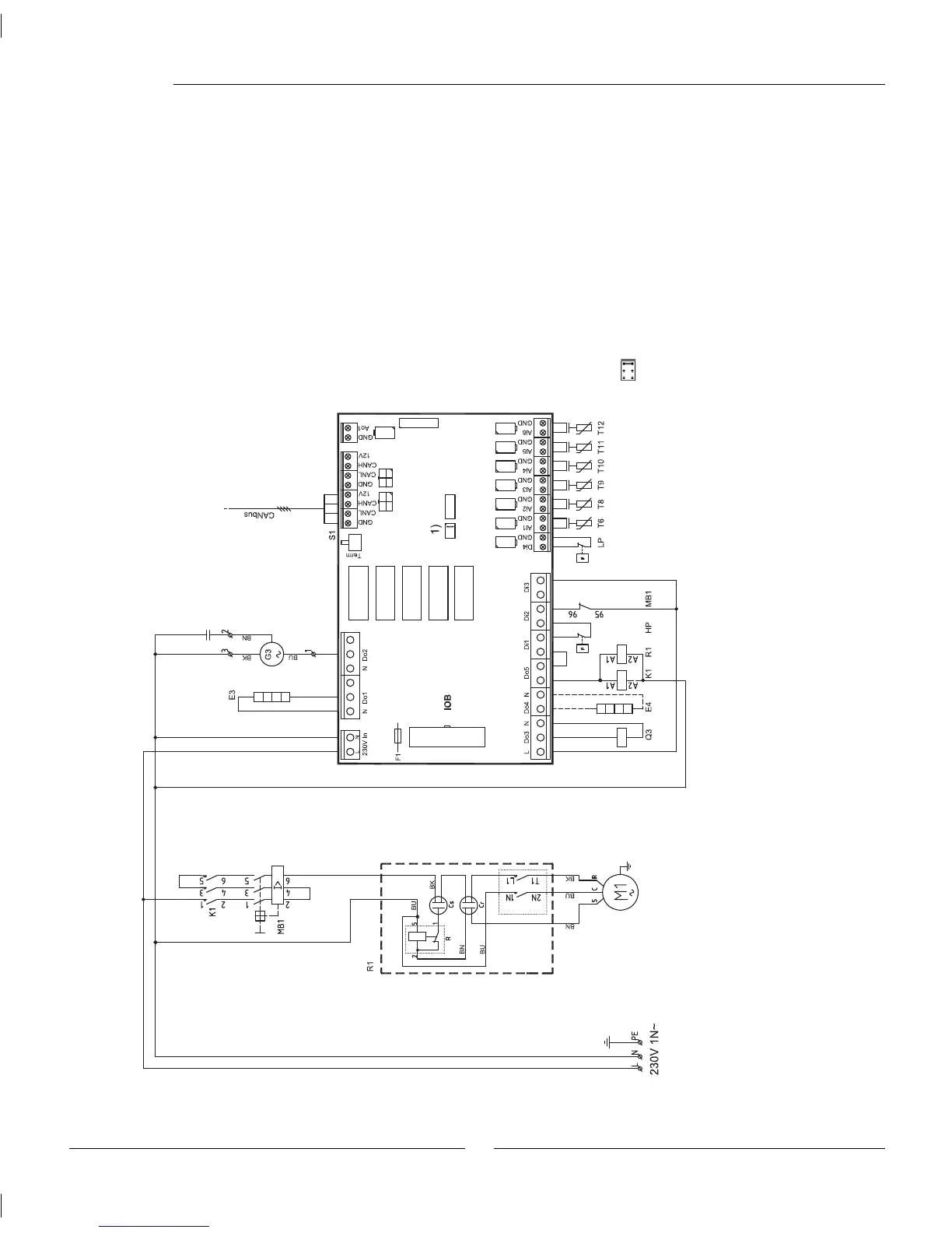
Wiring diagram Greensource heat pump
Wiring diagram
Cr: Start capacitor
Cs: Run Capacitor
E3: Crankcase heater
E4: Heating cable, accessory
F1: Miniature circuit breaker
G3: Fan
K1: Contactor Compressor
M1: Compressor
MB1: Motor cutout compressor
Q3: Four-way valve
R: Potential relay
R1: Soft starter
S1: Termination switch
Sensors
Hp: High pressure switch
LP: Low pressure switch
T6 Compressor hot gas
T8: Heat transfer fl uid out
T9: Heat transfer fl uid in
T10: Condenser
T11: Evaporator temp
T12: Air intake
S1 must be in "Term" position
on the fi rst and last circuit
board in the CANbus loop.
1) Jumper compressor type
To HWDU