24
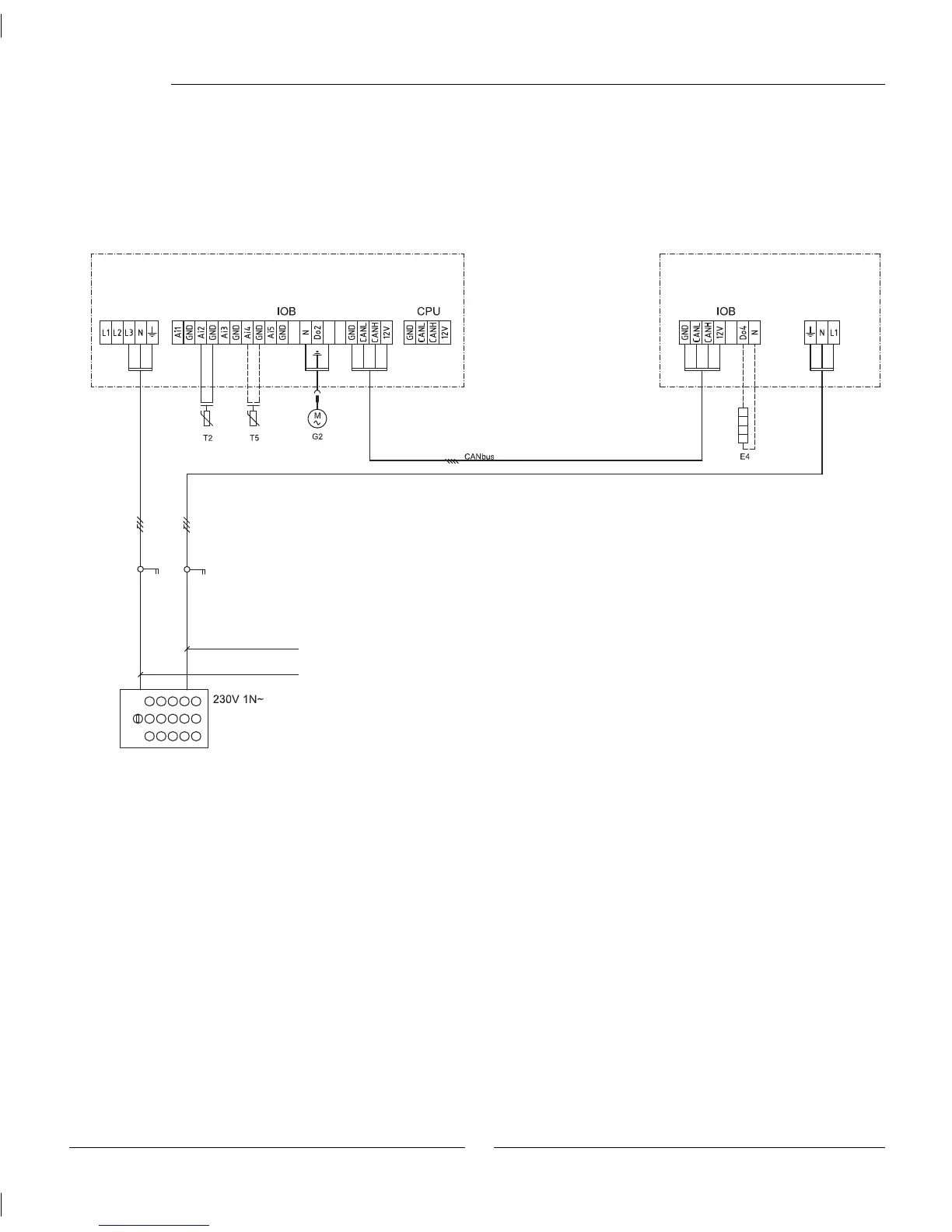
Terminal diagram Greensource heat pump - HWDU
G2: To protect the heat carrier pump G2 during stand alone operation of
HWDU it is not connected from the factory. If the heat pump is to be
used G2 is connected with the quick connector in
the distribution box.
T2: Outdoor sensor
T5: Room sensor
It is recommended that a separate residual current device is fi tted
to the heating system.
Isolation switch, not included.
Fusing:
Greensource 6 kW: 16A
Greensource 7 kW: 25A
Greensource 9.5 kW: 25A
HWDU
Heat pump
Measurement transformers
on the incoming supply to
the house fuse box.
Wiring diagram
HWDU: 25A
 Loading...