6 720 611 137 GB (03.02)
38
Maintenance
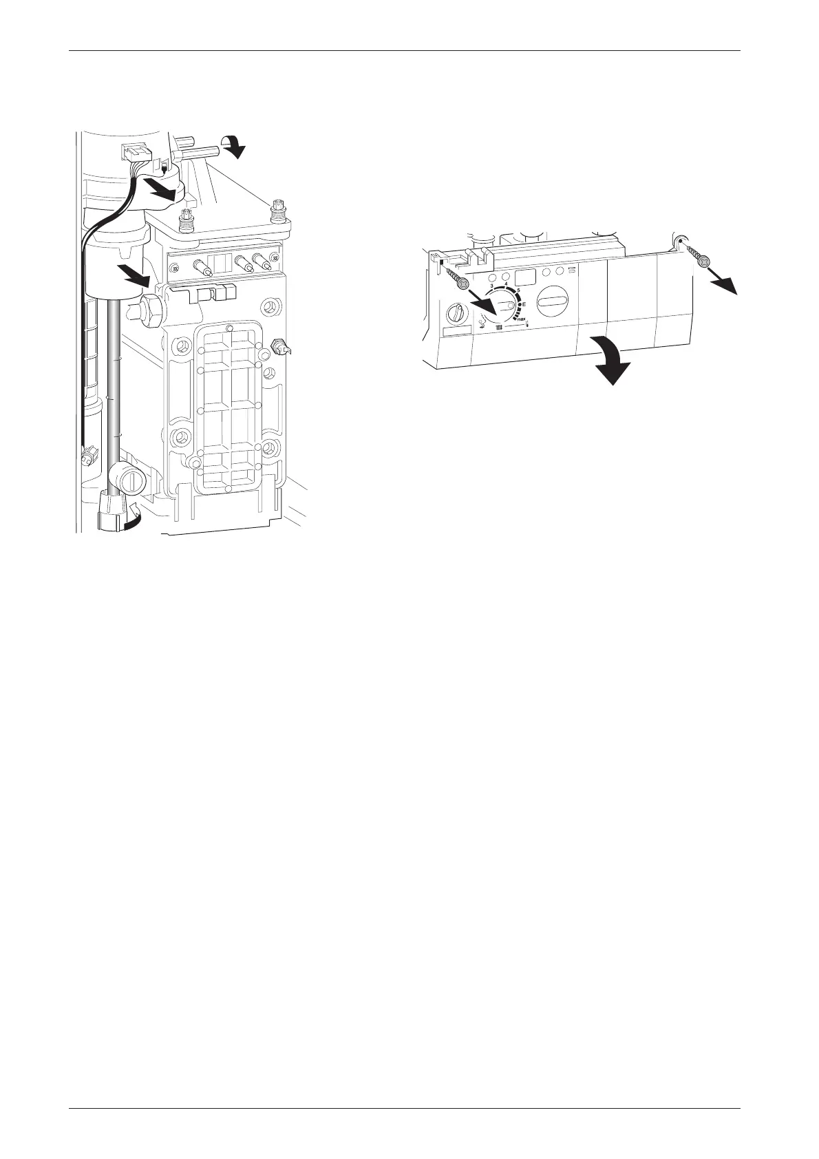
8.3.2 Fan Assembly
Fig. 59
B Switch off the appliance.
B Disconnect the appliance from the power supply.
B Undo lower pipe union on gas pipe (1.). Refer to
fig. 59.
B Remove fan lead and earth connector (2.). The earth
connector has a positive clip fixing.
B Remove fixing screws attaching fan to the burner
cover (3.).
B Remove fan together with gas pipe and mixer unit.
B Separate the fan from the pipe and mixer unit by
twisting the mixer unit to release it (4.).
8.3.3 Sensors
B Check that the appliance is electrically isolated.
Central Heating Flow Temperature Sensor –
Item 36, fig. 2, 57
B Pull-off the connector.
B Release the sensor clip and withdraw the sensor.
B Apply heat transfer paste to the replacement sensor.
Safety Temperature Limiter – Item 6, fig. 2, 57
B Pull-off the connectors.
B Unscrew the sensor.
Flue Temperature Limiter – Item 9, fig. 2, 57
B Pull-off the connectors.
B Unscrew the sensor.
8.3.4 Gas Valve
B Check that the gas cock is turned off.
B Lower the control panel. Refer to fig. 60.
Fig. 60
B Pull off the solenoid connections at the rear of the
valve.
B Undo the union, within the inner casing, securing the
valve to the gas/air tube. Refer to fig. 59.
B Remove the white plastic cap from the gas valve.
B Release the gas inlet union at the manifold assembly.
B Unscrew the two screws securing the gas valve
assembly bracket to the back panel and withdraw the
assembly.
B Transfer the bracket and inlet pipe assembly to the
new gas valve.
B Check for gas soundness when the new gas valve
has been fitted.
B Recheck the combustion performance as described
in section 7.1.
1.
2.
3.
4.
7 181 465 330-05.1R
2.
1.
1.
6 720 611 137- 25.1O