6 720 611 137 GB (03.02)
Maintenance
39
Fig. 61
8.3.5 Electrode assembly
B Refer to section 8.2.
B Use a new seal if the existing seal is damaged.
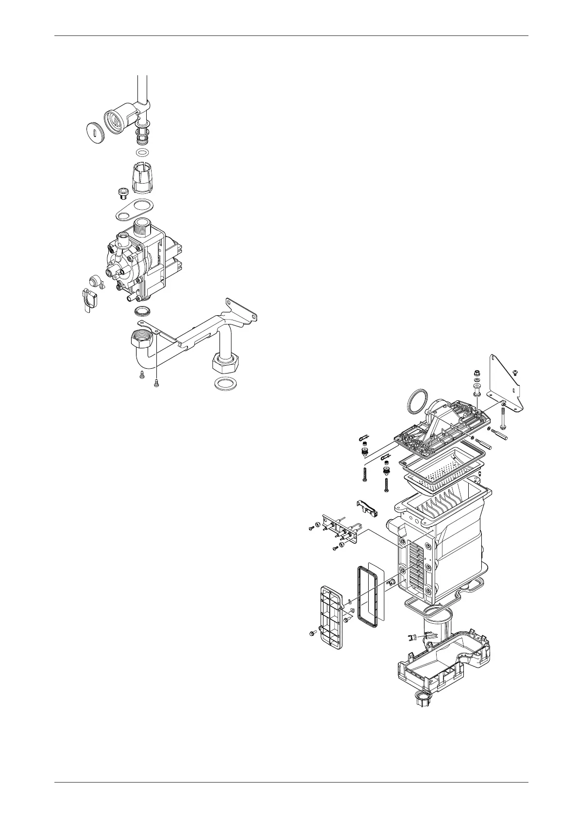
8.3.6 Pressure Relief Valve
B Drain the appliance.
B Disconnect the drain pipe from the valve. Refer to
fig. 32.
B Pull-out the clip securing the valve.
B Pull-out the valve.
B Ensure that the replacement valve is fully entered
before fitting the clip.
8.3.7 Burner
B Refer to section 8.2.
8.3.8 Primary Heat Exchanger
B Drain the appliance.
B Check that the gas supply is turned off.
B Check that the appliance is electrically isolated.
B Remove the fan assembly complete with the gas/air
tube and mixer assembly. Refer to section 8.3.2.
B Remove the burner. Refer to section 8.2.
B Disconnect the sensors. Refer to section 8.3.3.
B Undo the central heating flow union.
B Undo the grey plastic cap at the base of the heat
exchanger.
B Unscrew and remove the condensate trap. Refer to
section 8.2.
B Unscrew and remove the two screws securing the
heat exchanger top bracket to the rear panel.
B Lift up the flue duct, item 271, refer to fig. 2.
B Pull forward from the top and lift the heat exchanger
from the casing.
B Transfer components, as necessary, to the new heat
exchanger.
B Ensure that all the seals are in place and all of the
connections are tight before re-commissioning the
appliance.
Fig. 62
6 720 610 602 - 04.1O
6 720 610 602 - 06.10