COMMISSIONING
6 720 803 800 (2012/11)30
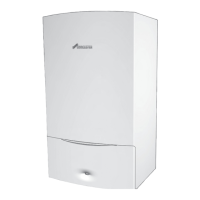
EXTERNAL 230V PROGRAMMER AND ROOM THERMOSTAT
Fig. 56 Room thermostat with programmer
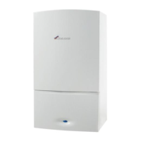
ROOM THERMOSTAT ONLY
Fig. 57 Room thermostat with plug in timer
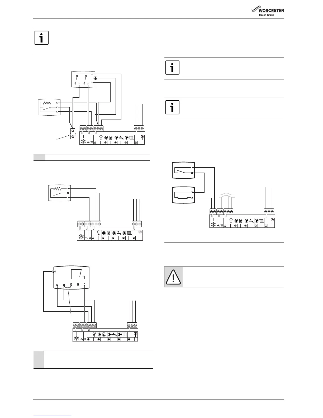
PROGRAMMABLE THERMOSTAT
Fig. 58 Programmable thermostat
▶ Remove the link between L
R
(CH) and L at the 230V OUT terminal
block connection.
▶ Connect external controls LIVE supply to terminal L at the 230V OUT
terminal block connection.
▶ Connect external controls LIVE return to terminal L
R
(CH)
▶ Connect external controls NEUTRAL to terminal N at the 230V OUT
terminal block connection.
OPTIONAL EXTERNAL FROST STAT CONNECTION FOR PROTECTION
OF SYSTEM PIPEWORK IN UNHEATED AIR SPACE
▶ Connect frost thermostat cables to terminals F
S
& F
R
.
▶ These connections are not polarity sensitive.
▶ The external frost thermostat only operates the pump.
Fig. 59 Frost Thermostat
5 COMMISSIONING
5.1 PRE-COMMISSIONING CHECKS
Check that the service and water pipes are connected to the correct
positions on the manifold.
Ensure that the washers have been fitted to the water connections and
the bonded washer to the gas connection on the manifold, refer to
Fig. 32.
1. - CH Flow (22mm)
2. - DHW (15mm)
3. - Gas inlet - bonded washer (22mm)
4. - Domestic cold mains water in (15mm)
5. - CH Return (22mm)
▶ Check the gas type specified on the data label, on the right hand side
of the combustion chamber, matches that of the gas supply.
▶ Turn on the main gas supply, carry out a tightness test on the gas pipe
work with the boiler gas pipe isolating valve open, and connections.
Rectify any leaks.
▶ Check that the condensate pipe has been connected and correctly
fitted to the siphon.
▶ Check pressure relief drain pipe is correctly fitted and securely
tightened.
The programmable room thermostat may be a hard
wired or RF type.
This diagram is applicable for a hard wired unit or the
receiver section of the RF pack.
1 Series connector, not supplied. Connector to be made safe.
1 The link between the Live (L) and Common (C) may already be
fitted as part of the Programmable thermostat, if not then a link
must be wired in.