SERVICE AND SPARES
6 720 803 800 (2012/11) 51
6.8.29 REPLACING THE CONTROL UNIT
With the installer access cover removed:
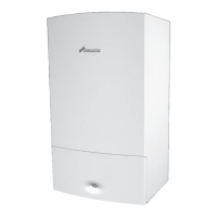
1.Remove all the connectors
2.Slide out all the cable strain relief clamps
Fig. 118 Disconnect external connections
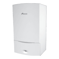
With the control unit in the service position:
1.Remove the single cover retaining screw.
2.Release the catches and remove the access cover.
▶ Lift the HCM (3) from the retainer and disconnect the cable, keep the
HCM to fit into the new control unit.
▶ Disconnect and remove all cables and connectors from the control
unit.
▶ Remove the pressure gauge, refer to section 6.8.20.
Fig. 119 Access to the cables
[1] Low voltage cable inlet
[2] Mains voltage cable inlet
[3] HCM - Heating Control Module
[4] Pressure gauge
[5] Low voltage connectors
[6] Mains voltage and earth connectors
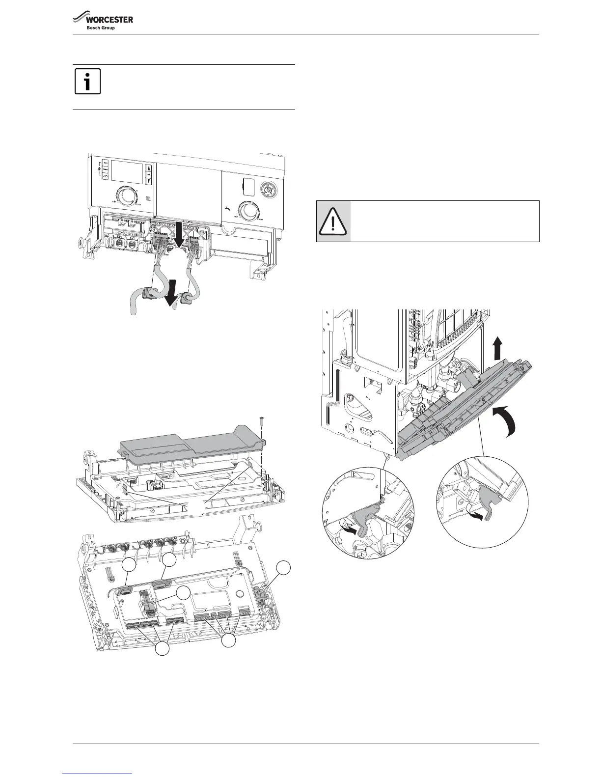
REMOVING THE CONTROL UNIT
▶ Support the control unit and detach the control unit support strap.
1. Release the two catches underneath the panel.
2. Hinge the control unit up to approximately a 45° angle.
3. Push inwards and upwards to disengage the control unit from the
hinge supports.
▶ Remove the support strap from the control unit.
▶ Fit the new control unit in the reverse order.
▶ Attach support strap to the new control unit.
▶ Fit the HCM, removed from the old control unit, into the retainer and
reconnect the cable.
▶ Reconnect all the cables previously disconnected under the access
cover.
▶ Replace the access cover and secure with the screw.
▶ Reconnect the cables previously disconnected under the installer
access cover.
▶ Replace the installer access cover and secure with the three screws
removed earlier.
Fig. 120 Removing the controller
6.8.30 EXPANSION VESSEL
The expansion vessel can be replaced with the boiler in place if there is a
side exit flue fitted and a minimum clearance of 450mm above the boiler
casing.
If a vertical flue is fitted then a similar clearance to one side of the flue is
required.
If the clearance is not available, then the boiler will need to be removed
from the mounting frame to gain access to the expansion vessel.
Alternatively, a second vessel of at least the capacity of seven litres can
be fitted to the return pipe from the heating system as close as possible
to the boiler.
The control unit is supplied in a plastic housing. The
complete unit must be replaced.
The HCM must be exchanged from the old to the new
control unit.