SERVICE AND SPARES
6 720 803 800 (2012/11) 39
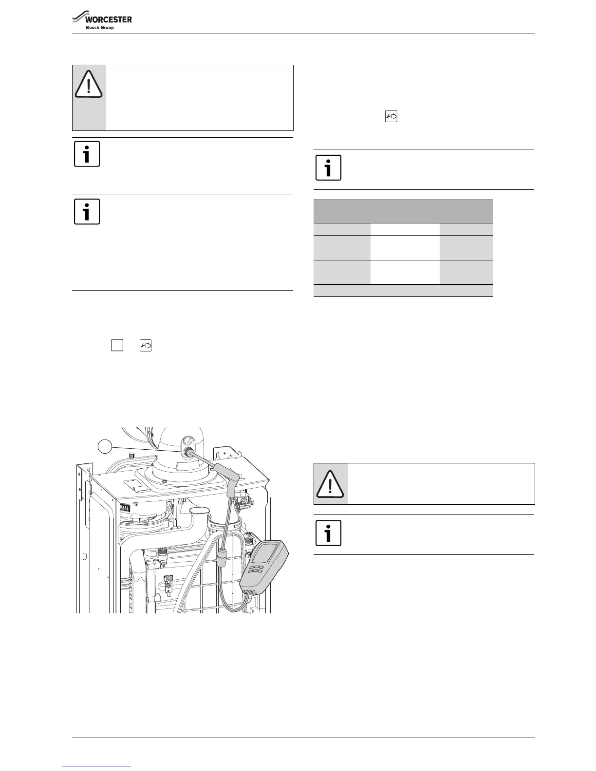
6.6 FLUE GAS ANALYSIS
COMBUSTION TEST
▶ Connect the flue gas analyser to the flue gas sampling point (1) as
shown in the figure below.
▶ Ensure that the probe reaches the centre of the flue gas exhaust,
adjust the cone on the probe so that it seals the sample point and
correctly positions the end of the probe.
▶ Press the and buttons together
– The chimney sweep symbol will be displayed at the top of the
screen.
– “Max” will flash at the bottom of the screen.
– The boiler will ramp up to maximum output in approximately 30 to
35 seconds.
▶ Run the boiler at maximum output for at least 10 minutes.
▶Check the CO/CO
2
readings against the information in table 16.
Fig. 76 Combustion test
▶ Check CO is less than 200ppm.
▶ Set the boiler to minimum power by pressing the down arrow button.
– “Min” will flash at the bottom left of the screen.
– The boiler will take 30 to 35 seconds to ramp down to minimum
output.
– Allow the boiler to stabilise at minimum output.
▶ Check that the CO is less than 200ppm.
▶ Return the boiler to maximum, by pressing the UP arrow button, and
re-check the CO/CO
2
.
– “Max” will flash at the bottom left of the screen.
– The boiler will take approximately 30 to 35 seconds to ramp up to
maximum output.
– Allow the boiler to stabilise at maximum output.
▶ If correct, press the button and the boiler will return to normal
operation.
▶ Re-assemble and refit boiler case.
If the CO
2
is out of tolerance then please check:
▶ the gas inlet pressure,
▶ the gas rate,
▶ the fan test pressure,
▶ the condition of burner,
▶ the flue and air intake, plus any possible blockages in the condensate
disposal.
▶ for leaks or obstructions in the gas way,
▶ that the injector is clean.
After all checks have been and the CO
2
is still out of tolerance then the
gas valve must be replaced.
6.7 CLEANING THE HEAT EXCHANGER
The following items will have to be removed to gain access to the heat
exchanger for cleaning:
▶ Lower the control panel into the service position.
▶ Remove the case.
▶ Disconnect electrical wires to the fan, ignition transformer, spark
electrodes, flue overheat thermostat, main heat exchanger
temperature sensor and flow pipe temperature sensor.
▶Flueway
▶Fan assembly
▶ Ignition transformer
▶ Spark electrode assembly
▶ Burner housing, burner and gasket
Refer to sections 6.8.9 to 6.8.13 for instructions on how to remove the
items to gain access to the heat exchanger channels so that the heat
exchanger can be cleaned
NOTICE: Combustion testing
▶ Combustion testing must be carried out by a
competent person. Testing must not be attempted
unless the person carrying out the combustion check
is equipped with a calibrated Combustion Analyser
conforming to BS 7927 and is competent in its use.
Ensure that the gas inlet pressure has been checked and
is satisfactory, refer to section 5.5.1
When running in maximum output, and the water
temperature is 65°C or less, the boiler will operate both
the central heating and DHW circuits with the diverter
valve in the mid position. It will be necessary to run
sufficient water through the DHW circuit to ensure that
the boiler will not cycle on low heating demands.
This is to allow sufficient time for the setting procedure.
When the water temperature reaches 75°C the diverter
valve will switch to CH only.