SERVICE AND SPARES
6 720 803 800 (2012/11) 45
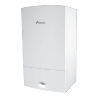
FAN REMOVAL
3.Rotate the exhaust pipe anticlockwise to gain access to the fan
assembly securing screws.
4. Support the weight of the fan and remove the two screws securing the
fan.
Fig. 94 Fan removal 1
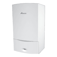
5.Rotate the exhaust pipe clockwise.
6.Pull the fan assembly away from the mount, lift and rotate the fan
towards you. Ensure that the front of the fan clears the left hand front
castellated nut securing the burner housing.
7.Pull the gas pipe off the fan body connection, the pipe is secured by
the interference fit between the pipe and connector.
Fig. 95 Fan removal 2
6.8.10 AIR/GAS FLAP VALVE ASSEMBLY
1. Remove the single screw securing the air/gas flap valve assembly.
2. Pull the flap assembly away from the housing.
Fig. 96 Air/gas flap valve
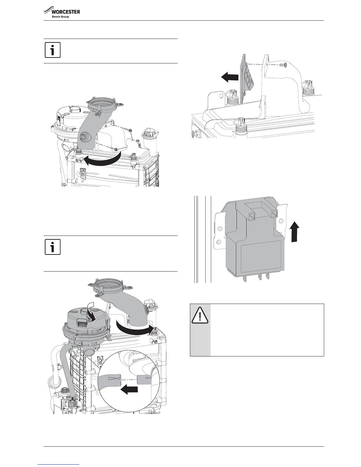
6.8.11 IGNITION TRANSFORMER
To remove the ignition transformer
▶ Isolate the boiler electrically.
▶ Remove the combustion air inlet pipe.
▶ Ensure that the harness wires are disconnected from the transformer.
▶ Remove the electrode cables.
▶ Lift the transformer from the retaining clip.
Fig. 97 Ignition transformer
6.8.12 ELECTRODE ASSEMBLY
To remove the spark electrode assembly:
1. Undo and remove the two nuts securing the electrode assembly
2. Rotate the electrode assembly down and forward to remove from the
Heat exchanger.
▶ Inspect the spark electrodes (2), ionisation probe (3) and ceramics
for signs of contamination or damage, replace as necessary.
▶ If necessary, clean the spark electrodes and ionisation probe with a
plastic scouring pad.
▶ Re-assemble with a new electrode gasket (1),
The boiler case is shown removed to aid clarity.
When refitting the rubber gas pipe, ensure that the pipe
is correctly oriented by aligning the notch in the pipe
with the lug on the fan connector. Do not kink the pipe.
There is a raised arrow on the pipe indicating the location
of the notch.
CAUTION: Component replacement:
▶ After replacement of a gas related component, where
a gasket or seal has been disturbed or replaced, check
for gas tightness using a gas sniffer/analyser.
▶Also after re-assembly, carry out the following
checks:
Fan pressure in section 6.5,
Flue gas analysis in section 6.6.