SERVICE AND SPARES
6 720 803 800 (2012/11)48
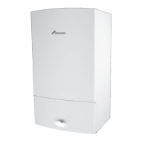
Fig. 105 Pump head removal
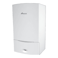
6.8.18 FLOW SENSOR, FLOW RESTRICTOR AND FILTER REMOVAL
▶ Isolate the cold mains and ensure that the DHW circuit is fully drained.
▶ Disconnect the electrical connection to the turbine.
▶ Undo the nut connecting the flow sensor assembly elbow to the Cold
Mains isolating valve.
1.Remove the clip from the housing.
2.Pull the flow sensor assembly out.
3.Remove the flow regulator (1) from the turbine assembly (2).
4.Remove the clip from the flow sensor assembly.
5.Separate the elbow (3) from the turbine assembly (2).
6.Remove the filter (4).
Fig. 106 Flow sensor assembly
6.8.19 FLOW REGULATOR
The flow regulator can be further broken down into:
1 - Spacers
2 - Flow regulator
3 - Flow regulator housing
Fig. 107 Flow regulator assembly
6.8.20 PRESSURE GAUGE
▶ Ensure that the boiler is fully drained.
1. Carefully prise the lugs apart.
2. Remove the pressure gauge.
3. Withdraw the spring clip from the pressure sensing head housing.
4. Remove the pressure sensing head and pressure gauge capillary from
the housing.
Fig. 108 Pressure gauge removal
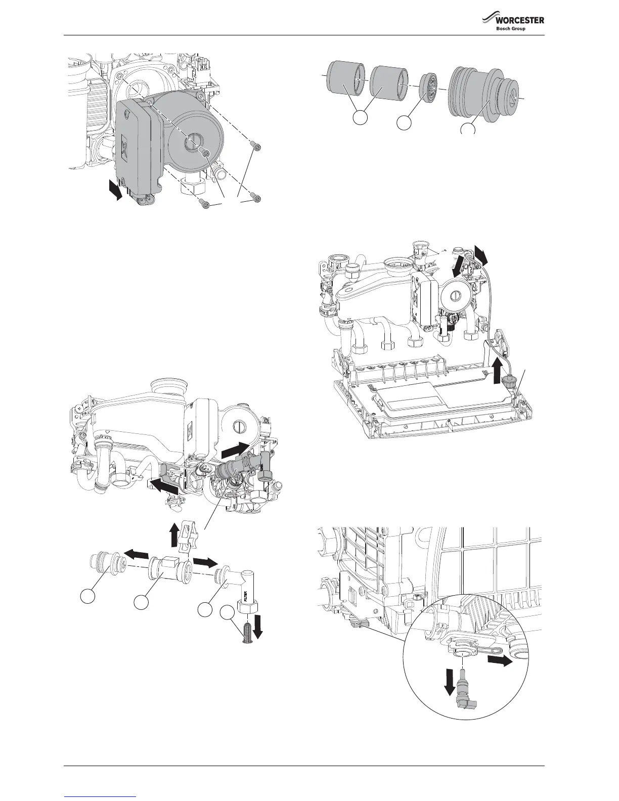
6.8.21 BOILER RETURN SENSOR (NTC)
▶ Isolate the boiler and ensure that the boiler is fully drained.
1. Withdraw the spring clip to release the sensor.
2. Pull the sensor down to remove from the housing.
▶ To refit follow the above actions in reverse.
Fig. 109 Boiler return sensor