INSTALLATION
INSTALLATION & SERVICING INSTRUCTIONS
18
MOUNTING FRAME FIXING &
FLUE OPENING
8 716 115 216b (09.2008)
MOUNTING FRAME FIXING &
FLUE OPENING
38mm
XY Z
All dimensions in mm
20
65 65
CB A
A
D
E
3
X
123
2
1
4
Z
Y
143
123
743
267
B
20
F
DD
70.5
CAUTION: Ensure there are no pipes,
electric cables, damp proof course or other
hazards before drilling.
SAFETY:
All relevant safety precautions must be
undertaken. Protective clothing, footwear,
gloves and safety goggles must be worn as
appropriate.
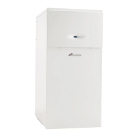
MOUNTING FRAME/PIPEWORK POSITIONS:
A - Mounting frame.
B - Manifold connections.
C - Mounting frame fixing point.
D - Wall.
E - Gas and water pipework (not supplied).
F - Boiler.
FIXING THE MOUNTING FRAME:
Position the mounting frame (A) on the
floor against the wall with manifold
connections (B) facing away from the wall
(D) ensuring there is enough space for the
pipework (E).
Allow the minimum space from each side
of the frame (A) for the boiler overhang (F)
and minimum service clearance, as shown.
Ensure the mounting frame is level and
mark fixing points (C).
Secure mounting frame (A) to the floor
using appropriate fixings (not supplied).
Clear any debris from the site.
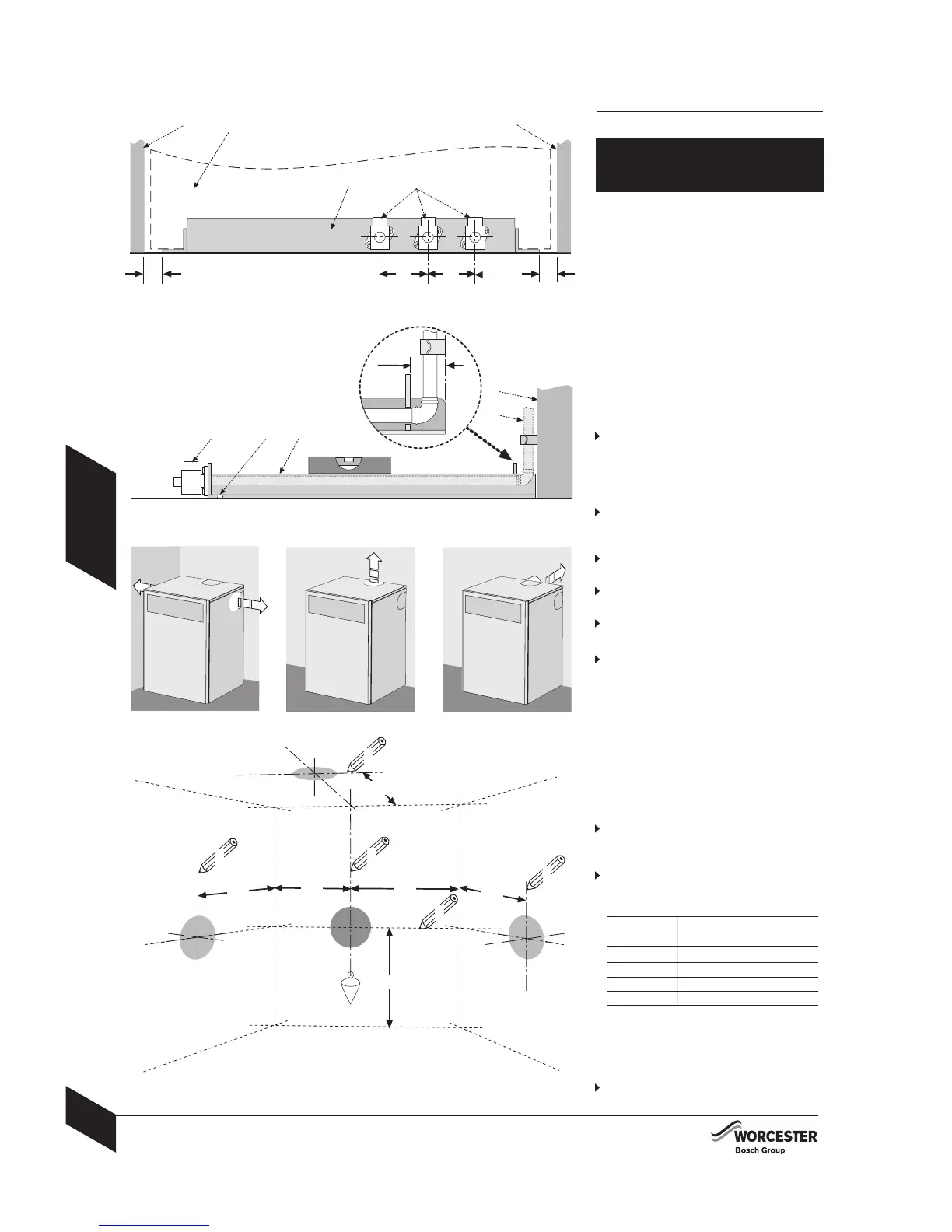
FLUE OPENING:
Follow the diagram opposite to mark the
centre of the flue (1, & 2) for rear opening,
(2 & 3) for side opening or (1 & 4) for top
opening.
Measurements shown include the minimum
service clearances.
NOTE: All horizontal flue sections must rise away
from the boiler by 52mm per meter to
ensure that condensate flows back into
the boiler for safe discharge via the
condensate waste pipe.
Cover the mounting frame manifold
assembly (A) to protect the manifold
connections.
Make an opening (X or Z) through the wall
using a core drill or similar at a size relative
to the wall thickness as shown below:
Wall Flue opening Flue opening
thickness 60/100mmØ 80/125mmØ
150 - 240mm 127mmØ 152mmØ
240 - 330mm 127mmØ 152mmØ
330 - 420mm 127mmØ 162mmØ
420 - 500mm 140mmØ 162mmØ
Where the flue terminal can only be fitted
from inside the building, increase the opening
to 150mmØ to allow the optional weather
collar to fit through the opening for 60/100
flue.
Clear away any debris.
3
123