IN STALLATION
INSTALLATION & SERVICING INSTRUCTIONS FOR WORCESTER BOSCH
25
ELECTRICS
ELECTRICS
8-716-106-256a (08.05)
DANGER - 230V:
ISOLATE THE MAINS ELECTRICITY
SUPPLY BEFORE STARTING ANY
WORK AND OBSERVE ALL
RELEVANT SAFETY PRECAUTIONS.
IMPORTANT: OBSERVE ELECTRONIC
STATIC DISCHARGE PRECAUTIONS. DO
NOT TOUCH THE PCB CIRCUITS
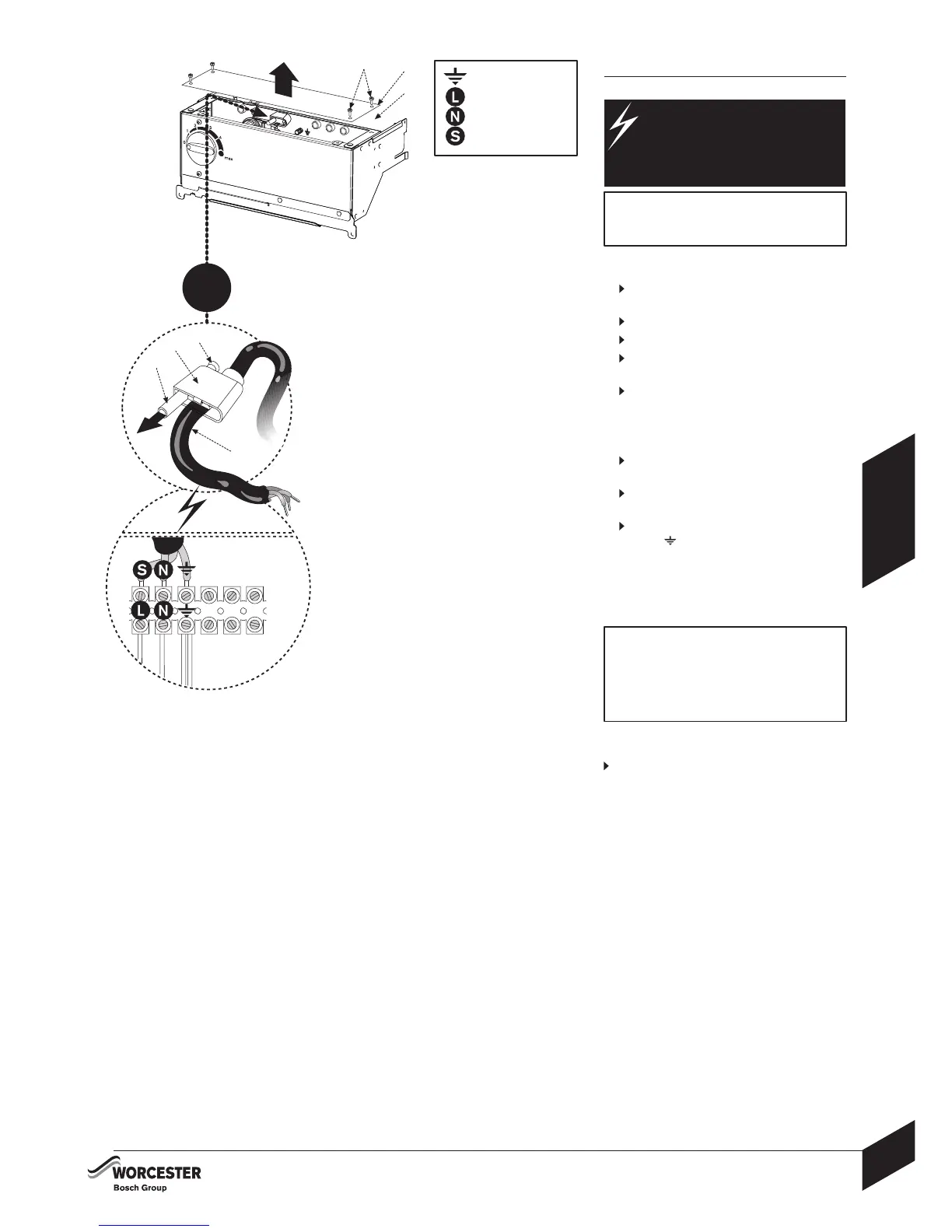
Access to 230V connections:
1
Release screws (B) and remove cover panel
(C) from control box (A).
2
Release screw (D) from cable clamp (E).
Pull inner clamp part (F) outwards.
Feed sufficient power cable (G) through the
cable clamp (E) and secure grip with screw (D).
Separate wires from cable end and strip to
6mm.
230V connections:
3
Connect SWITCHED LIVE wire (Brown or
Red) to terminal (L).
Connect NEUTRAL wire (Blue or Black) to
terminal (N).
Connect EARTH wire (Green/Yellow) to the
terminal (
).
Route the power cable to the connection point
avoiding any potentially hot surfaces with sufficient
cable to move the control box into the service
position. Open the control box into the service
position to check the cable length and routing.
Any external device connected to the boiler
must take its power supply from the boiler
supply only and must NOT have a separate
power supply.
See the following pages of electrical
diagrams for details of different systems.
Refit electric control panel cover:
Refit cover panel (C) to control box (A) and
secure with screws (B).
230V
G
C
A
B
1
D
E
F
2
230V
3
123
= EARTH
= LIVE
= NEUTRAL
= SWITCHED LIVE