Page 17 of 39 WIM-TD-002_C
3.2.0 OUTBOARD SUPPORT (if required)
3.2.1 Refer to Table 1 for the necessity of using an outboard support.
OUTBOARD SUPPORT REQUIREMENT
3.2.2 When installing a support bracket, ensure the PTO maintains proper alignment throughout the
flywheel, bellhousing & shaft. A dial indicator may be used to verify the PTO is not moving or
deflecting during the installation process (see section 3.1). Shim and adjust the support as needed.
NOTE: the outboard support should complement the position of the PTO, not change it.
WARNING:
Adhere to Table 1 regarding the necessity of an outboard support. The outboard support should not restrict flexure
of the engine mounts. Failure to provide adequate support can result in personal injury and/or damage to the PTO.
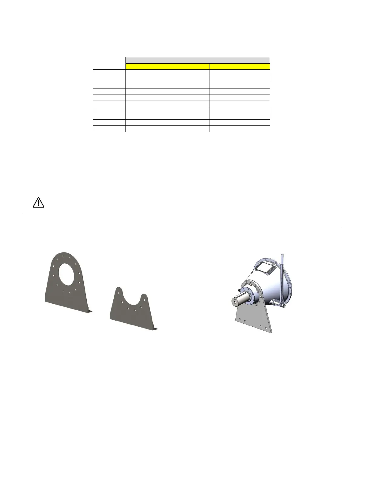
3.2.3 See Figure 1 for Outboard support examples.
3.2.4 Models may vary, refer to assembly drawing for mounting requirements. Apply torque to outboard
support hardware in accordance with TABLE 7.
3.2.5 PTO deflection due to loads imposed by application should not exceed 0.010 in [0.254 mm].
deflection should be measured at the support plate pilot with dial indicator base mounted on a
rigid part of the engine. (see section 3.1)