ENGINE
WG972-E4, WSM
1-S53
Oil Clearance between Crankpin and Crankpin Bearing
1. Clean the crankpin and crankpin bearing.
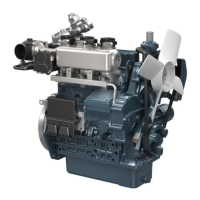
2. Put a strip of plastigage on the center of the crankpin.
3. Install the connecting rod cap and tighten the connecting rod
screws to the specified torque, and remove the cap again.
4. Measure the amount of the flattening with the scale, and get the
oil clearance.
5. If the oil clearance exceeds the allowable limit, replace the
crankpin bearing.
6. If the same size bearing is useless because of the crankpin
wear, replace it with an undersize one referring to the table and
figure.
• Never insert the plastigage into the crankpin oil hole.
• Be sure not to move the crankshaft while the connecting
rod screws are tightened.
(Reference)
• Undersize crankpin bearing
• Undersize dimensions of crankpin
9Y1211108ENS0093US0
Oil clearance between
crankpin and crankpin
bearing
Factory specification
0.020 to 0.051 mm
0.00079 to 0.0020 in.
Allowable limit
0.15 mm
0.0059 in.
Crankpin O.D. Factory specification
33.959 to 33.975 mm
1.3370 to 1.3375 in.
Crankpin bearing I.D. Factory specification
33.995 to 34.010 mm
1.3384 to 1.3389 in.
Undersize Bearing Code Number Marking
0.2 mm
0.008 in.
Crankpin bearing 02 15861-22970 020 US
0.4 mm
0.02 in.
Crankpin bearing 04 15861-20980 040 US
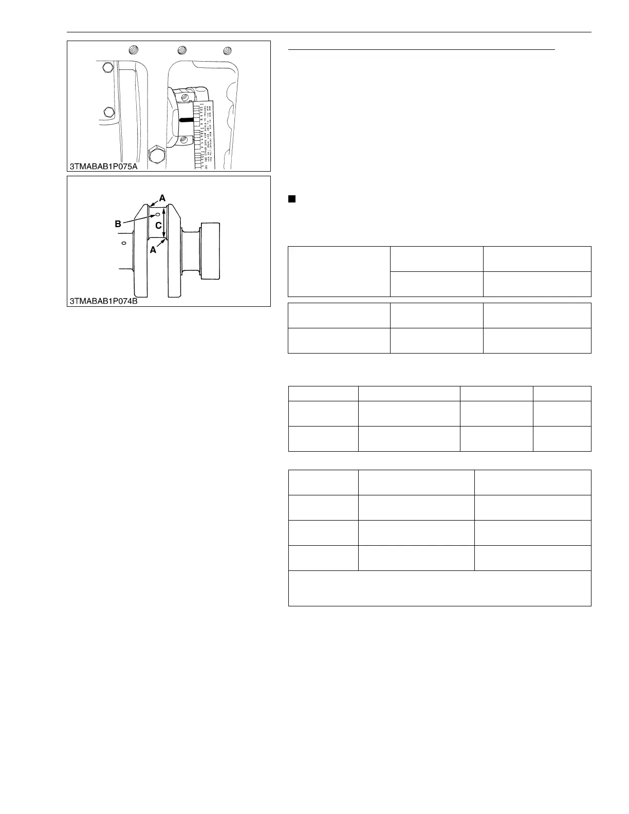
Undersize
0.2 mm
0.008 in.
0.4 mm
0.02 in.
Dimension A
2.3 to 2.7 mm radius
0.091 to 0.10 in. radius
2.3 to 2.7 mm radius
0.091 to 0.10 in. radius
*Dimension B
1.0 to 1.5 mm relief
0.040 to 0.059 in. relief
1.0 to 1.5 mm relief
0.040 to 0.059 in. relief
Dimension C
33.759 to 33.775 mm dia.
1.3291 to 1.3297 in. dia.
33.559 to 33.575 mm dia.
1.3213 to 1.3218 in. dia.
The crankpin journal must be fine-finished to higher than Rmax = 0.8S
*Holes to be de-burred and edges rounded with 1.0 to 1.5 mm
(0.040 to 0.059 in.) relief.