ENGINE
WG972-E4, WSM
1-M26
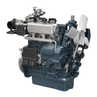
Total Wave Rectification
In case of the generator for mobile equipment of
which purpose is to charge the batteries, alternating
current cannot be used as it is. Because of this, it is
required to conduct the action called rectification so that
the alternating current can be changed to direct current.
Alternator conducts rectification by means of diode.
If the voltage is applied to diode in the normal
direction, enough electrical current can flow even by
small voltage, however if applied in the reverse direction,
it inhibits the reserve flow of electrical current.
Using this property, alternate current generated in
the stator coil is changed to the direct current.
As for the rectification using diode, there are two
methods, i.e., "half-wave rectification" that removes only
positive portion of alternate current, and 'total-wave
rectification' that rectifies both positive and negative
current and change to the direct current.
9Y1211108ENM0048US0
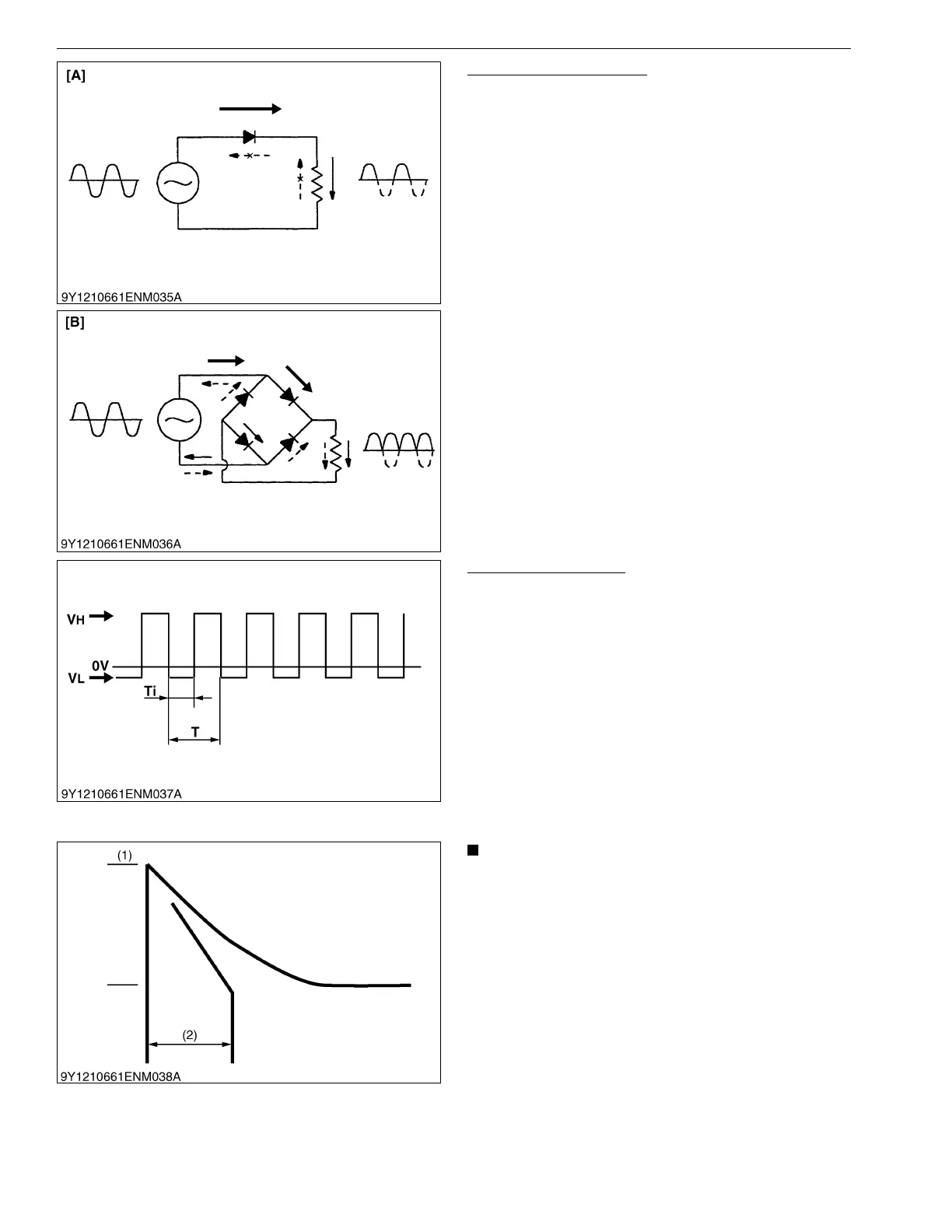
Alternator P Terminal
P terminal waveform: The alternator P terminal
outputs rotation signals required by a tachometer, etc.
The P terminal corresponds with one phase of the
alternator stator and the output waveform during power
generation is a waveform equivalent to the rectangular
wave with a frequency in proportion to the number of
revolutions of the alternator.
9Y1211108ENM0049US0
• As with the B terminal waveform, the P terminal
waveform includes noise, which varies
depending on the number of revolutions, output
and wiring (see the waveform in a separate
material).
• Surge voltage may be generated by any charging
cable disconnection (especially with high
number of revolutions / high output), etc.
9Y1211108ENM0050US0
[A] Half-wave Rectification [B] Total-wave Rectification
Frequency (1/T): Number of Revolutions of Alternator
[rpm] / 10 [Hz]
Duty (Ti/T): Approx. 50 %
VH (average): About +0 to 2 V with Reference to the
Alternator B Terminal Voltage (Average)
VL: About −2 to 0 V
(1) Approx. 150 V (2) Approx. 180 ms