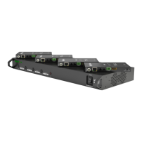
Connect HDMI sources (such as HD-DVD, Blu-ray,
games console, AppleTV, satellite/cable etc.) to HDMI
inputs 1 – 4 of the MATRIX.
Attention Do Not Hotplug! - Please insert and
extract cables carefully with the power SWITCHED
OFF. Connecting and disconnecting while the unit is
powered can result in damage to circuitry.
Attach the IR emitter directly over the infrared
receiving sensor of the input source using the adhesive
backing. You may need to adjust the position of the
emitter after installation to achieve the best results.
Sometimes moving the sensor to different areas of the
source can improve IR performance.
Plug the 3.5mm jack of the IR emitter into your
chosen number IR TX port on the rear panel of the
MATRIX.
For two-way IR control of the display from the matrix or
connection to a control system, connect an IR Link cable
to the control system or plug an IR RX receiver cable into
the corresponding IR RX port on the rear panel of the
MATRIX, ensuring the receiver is placed in clear view to
receive an IR signal.
NOTE Make sure the IR jacks are in the same number
ports.
HINT Locate the infrared sensor on devices by
shining a flashlight onto the display panel of sources
and look for a small sensor.
Connect a good quality, well terminated Cat5e/6
cable with an RJ45 connector wired to 568B standard
at both ends from the UTP Output port of the MATRIX to
the UTP In of the display receiver. If cascading an output,
connect the UTP to the UTP IN of the transmission
device.
Ensure both RJ45 connectors are pushed securely into
each port and supported by the connector strain relief
clip to prevent them from becoming loose. The quality
of termination for your RJ45 is essential. Poor quality
terminations lead to intermittent performance and longer
install times.
HINT Although all WyreStorm products are tested
using Cat5e as standard, we suggest using Cat6 as
the preferred cable due to its improved distribution
capabilities.
1
2
3
4
CONNECTION
8. Connection
Key
cat 5e/6
hdmi
rs232
ir tx
ir rx
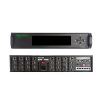
HDMI Source
display 1
Control
System
(additional
control
via
RS232)
IR TX emitter placed directly
over device IR window.
IR RX LINK Cable
connecting from Control
System to IR RX port of
matrix
IR TX emitter placed directly
over device IR window. IR
RX receiver placed discretely
on or near display device with
clear line of sight to remote
handset being used
Additional 12v
mains power
connection
(Optional)
24v DC
Power
Control
System
Cat5e/6 Wiring Guide
The quality of termination for every RJ45 is essential. Poor terminations
leads to intermittent performance and
longer install times.
Cat5e/6 Cable Performance Guide
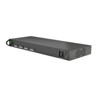
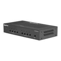
MX-0404-POH-KIT
0ft 328ft32ft 65ft 98ft 131ft 164ft 197ft 230ft 262ft 295ft
0m 100m
10m
20m 30m 40m 50m 60m 70m 80m 90m
1
2
3
3
4
6
5
7