Installation
14 975-0136-01-01
Connecting Your Xanbus System
Use an appropriate length of network cable to connect each device and 3-
way network connector (if used). See Figure 2 on page 1–5 and Figure 3
on page 1–6.
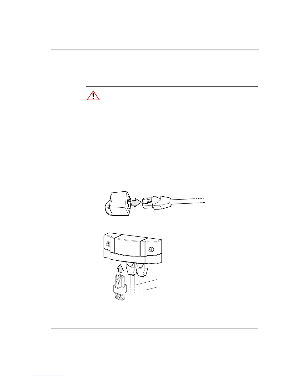
Completing the Multi-Drop Backbone Layout
To complete the multi-drop backbone layout:
◆ Attach a female terminator to the backbone cable at each end of the
network
Or
◆ Insert a male terminator into the open jack of the network connector
at each end of the network (see Figure 8).
CAUTION: Equipment Damage
Connect only to other Xanbus compatible devices.
Although the cabling and connectors used in this network system are the same as
ethernet connectors, this network is not an ethernet system. Equipment
damage may result from attempting to connect Xanbus to different systems.
Figure 8
Options for Completing a Multi-Drop Backbone Layout
Attach female terminator to
end of backbone cable.
Insert male terminator into
open jack of connector.
To previous
connector
To device
 Loading...