Installation
8 975-0136-01-01
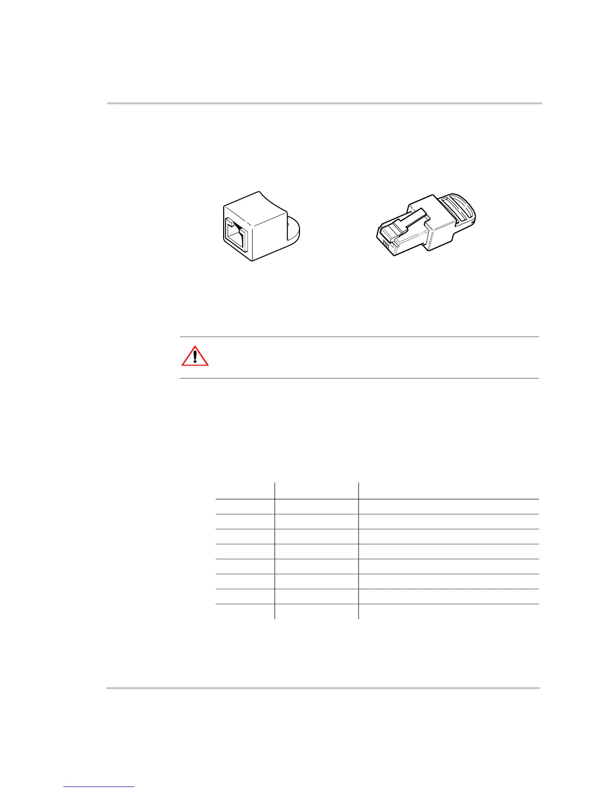
Terminators Terminators are required at both ends of the network to ensure the
communication signal quality on the network. The terminators are female
and male. See Figure 5.
The terminator requirements are different for each layout. See Figure 8
and Figure 9.
Cabling Requirements
Cabling The network uses Category 5 (CAT 5) cable, a standard cable available
from Xantrex or any computer supply store. The cable consists of eight
conductors in four twisted pairs with an RJ45 modular connector wired to
the T568A standard. Table 3 contains the arrangements of wire colors to
pin numbers for the T568A standard.
Figure 5
Network Terminators
CAUTION: Equipment damage
Do not use crossover cable in a Xanbus System.
Female terminator
Male terminator
Table 3
T568A Standard Wiring
Pin Number Conductor Name CAT 5 Cable Insulation Color
1 NET_S White/Green
2 NET_S Green
3 NET_C White/Orange
4 CAN_L Blue
5 CAN_H White/Blue
6 NET_C Orange
7 NET_S White/Brown
8 NET_C Brown
 Loading...