Installation
975-0136-01-01 5
Planning the Network
This section provides information on the following topics:
• two types of network layouts and the advantages and disadvantages
of each layout
• network components
• network connectors and/or terminators
• cable and connector requirements of each layout
• network power supply and network size
See “Installing the Network” on page 11 for instructions on routing and
layout.
Network Layouts
Xanbus-enabled devices can be connected in one of two Xanbus System
layouts: the multi-drop backbone or the daisy chain. Each network layout
has advantages and disadvantages, depending on the application and/or
environment. It is up to you or your system designer to decide which
layout is best for your installation.
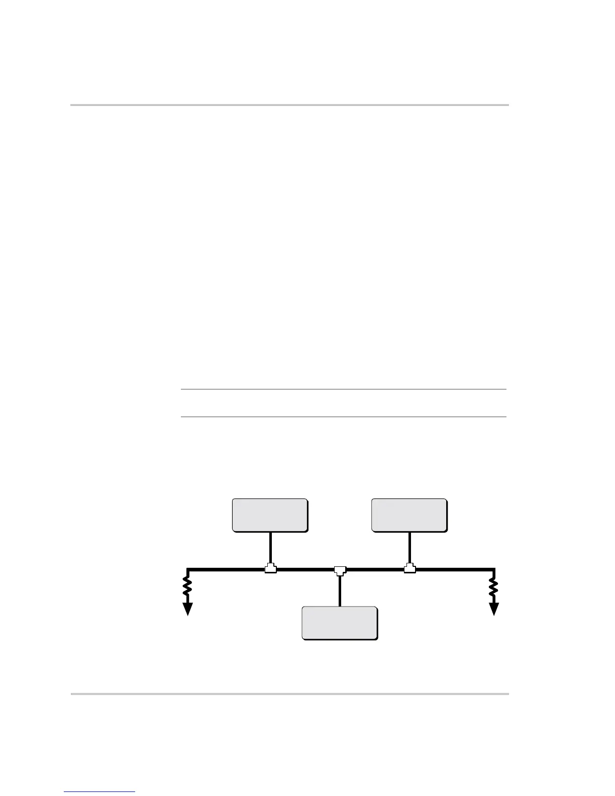
Multi-Drop Backbone Layout
In a multi-drop backbone layout, each Xanbus-enabled device on the
network is connected by a drop cable to the network bus or backbone with
a network connector, as shown in Figure 2.
Important:
Do not mix the two types of network layouts. Mixed
configurations are not supported by Xantrex.
Figure 2
Multi-Drop Backbone Layout
Xanbus-enabled
Device 1
Xanbus-enabled
Device 2
Xanbus-enabled
Device 3
Network
backbone cable
Network
connector
Drop cable
TerminatorTerminator
 Loading...