8 www.xilinx.com AC701 Getting Started Guide
UG967 (v3.0) July 10, 2013
Basic Hardware Bring-up with Built-In Self-Test
For a diagram of all features on the AC701 Board, see UG952, AC701 Evaluation Board for the
Artix-7 FPGA User Guide.
Test Setup Requirements
Note: This example design uses a Windows 7 PC flow and TeraTerm Pro.
The prerequisites for testing the design in hardware are:
• AC701 evaluation board with XC7A200T FPGA
• USB-to-Mini-B cable (for UART)
• USB-to-Micro-B JTAG cable
• AC Power Adapter (12 VDC)
• TeraTerm Pro or other terminal program
• USB-UART drivers from SiLabs [Ref 1]
• ISE® design tools or lab tools
• Vivado Design Suite installed on host PC
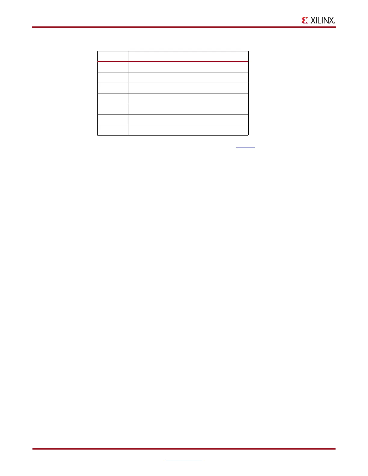
10 Prog button
11 Power slide switch
12 12V power connector
13 User DIP switch
14 Contrast wheel
15 User push buttons
16 USB-UART connector
Tabl e 1 : AC701 Board Features (Cont’d)
Callout Component Description

 Loading...


