AC701 Getting Started Guide www.xilinx.com 9
UG967 (v3.0) July 10, 2013
Basic Hardware Bring-up with Built-In Self-Test
Hardware Test Board Setup
This section details the hardware setup and use of the terminal program for running the
BIST application. It details step-by-step instructions for board bring-up. For more
information on installing the tools and drivers, see the Boards and Kits Install Guide
.
AC701 Evaluation Board Setup
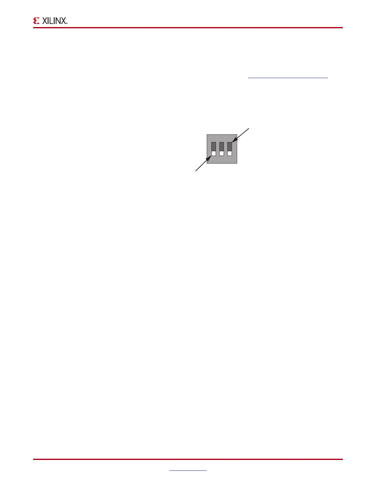
1. Set all three of the AC701 board SW1 switches to the OFF position as shown in
Figure 3.
Hardware Bring-up
This section details the steps for hardware bring-up.
1. With the board switched off, connect a USB-mini-B cable into the UART port of the
AC701 and the host PC (see Figure 4).
2. Connect the 12V adapter cable.
3. Connect the USB-A to USB-micro-B (Digilent JTAG) cable to the USB-micro-B port on
the AC701.
4. Switch AC701 Power to ON.
X-Ref Target - Figure 3
Figure 3: SW1 Switch Settings for JTAG Programming Mode
UG967_03_111412
SW1
1
OFF Position = 0
ON Position = 1
23
M2 M1 M0

 Loading...


