(https://reference.digilentinc.com/_detail/reference/programmable-logic/arty-a7/arty-a7-rev-e-power.png?id=reference%3Aprogrammable-
logic%3Aarty-a7%3Areference-manual)
Figure 3.1 Arty A7 Power Circuit
The USB port can deliver enough power for the vast majority of designs. However, a few demanding applications, including any that
drive multiple peripheral boards, might require more power than the USB port can provide. Also, some applications may need to run
without being connected to a PC’s USB port. In these instances an external power supply or battery pack can be used.
An external power supply can be used by plugging into Power Jack J13. The supply must use a coaxial, center-positive 2.1mm (or 2.5mm)
internal-diameter plug, and provide a voltage of 7 to 15 Volts DC. The supply should provide a minimum current of 1 amp. Ideally, the
supply should be capable of providing 36 Watts of power (12 Volts DC, 3 amps).
An external battery pack can be used by connecting the battery's positive terminal to pin 8 of J7 (labeled VIN) and the negative terminal
to pin 7 of J7 (labeled GND ()), as shown in Figure 3.2. The battery must provide a voltage between 7 and 15 volts DC, and should
NOT be installed while there is a supply connected to Power Jack J13.
(https://reference.digilentinc.com/_detail/arty/arty_rm_power-02.png?id=reference%3Aprogrammable-logic%3Aarty-a7%3Areference-manual)
Figure 3.2 Arty A7 Battery Pack Connection
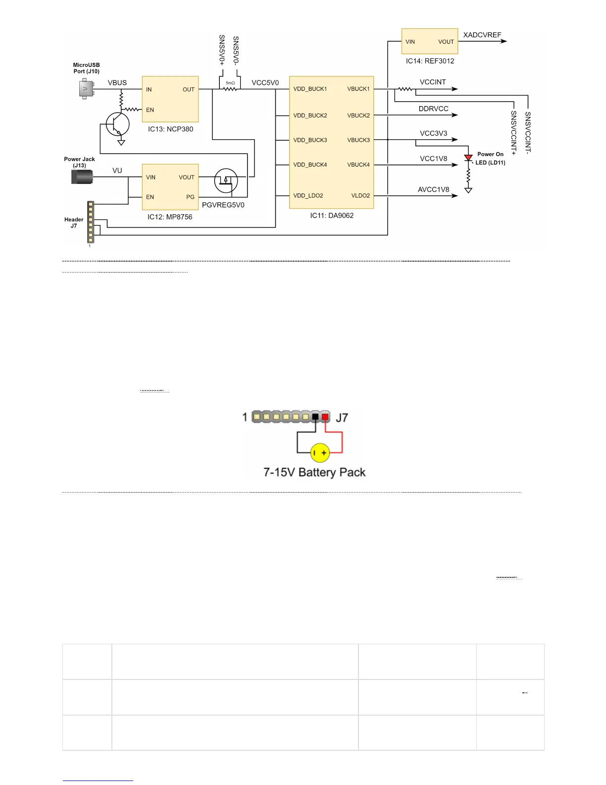
The Arty A7 uses a combination of a USB load switch (IC13), a MOSFET, (Q8), and some additional control circuitry to automatically
determine the 5V power source based on the supplies that are plugged into the board. If an external supply is connected to Power Jack
J13, it will be used as the input source regardless of whether or not anything is plugged into the USB port (J10). If the Arty A7 is initially
powered via USB and an external supply is plugged into J13, then the the 5V power source will automatically switch over to the regulated
external supply rail and no brown-out will occur. If the external supply is later disconnected from Power Jack J13 while USB power is still
present, then the 5V power source will switch over to USB power, and a brown-out - which can be seen as the power-good LED ()
toggles - will occur.
Voltage regulator circuits from Dialog Semiconductor and Texas Instruments create the required 3.3V, 1.8V, 1.35V, 1.25V, 1.00V,
0.675V supplies from the 5V power source. In the event that an external supply or battery pack is used, the on-board Monolithic Power
Systems 5V regulator (IC12) provides the 5V source. Table 3.1 provides additional information (typical currents depend strongly on
FPGA configuration and the values provided are typical of medium size/speed designs).