corresponding signals need to be driven high. The tri-color LED () will emit a color dependent on the combination of internal LEDs that
are currently being illuminated. For example, if the red and blue signals are driven high and green is driven low, the tri-color LED () will
emit a purple color.
Note: Digilent strongly recommends the use of pulse-width modulation (PWM) when driving the tri-color LEDs. Driving any of the
inputs to a steady logic ‘1’ will result in the LED () being illuminated at an uncomfortably bright level. You can avoid this by ensuring
that none of the tri-color signals are driven with more than a 50% duty cycle. Using PWM also greatly expands the potential color palette
of the tri-color led. Individually adjusting the duty cycle of each color between 50% and 0% causes the different colors to be illuminated
at different intensities, allowing virtually any color to be displayed.
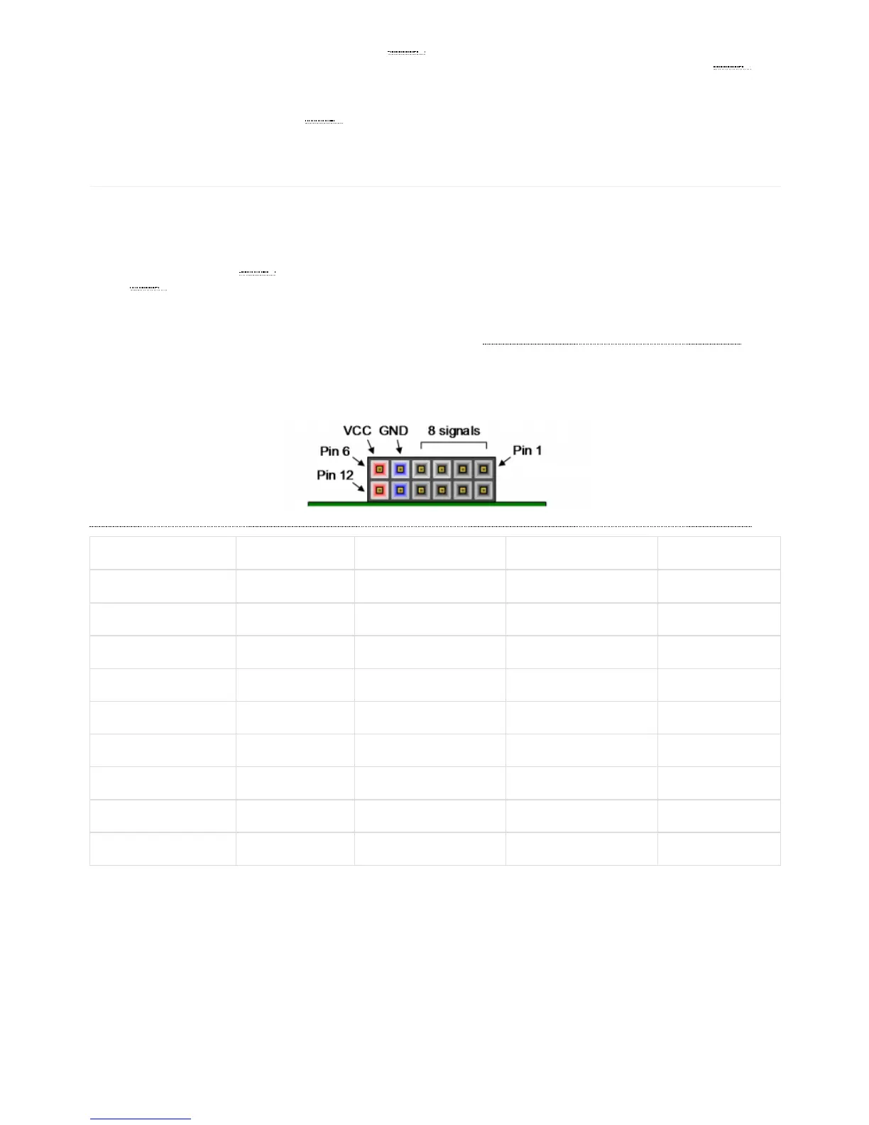
Pmod connectors are 2×6, right-angle, 100-mil spaced female connectors that mate with standard 2×6 pin headers. Each 12-pin Pmod
connector provides two 3.3V VCC () signals (pins 6 and 12), two Ground signals (pins 5 and 11), and eight logic signals, as shown in Fig.
16. The VCC () and Ground pins can deliver up to 1A of current, but care must be taken not to exceed any of the power budgets of the
onboard regulators or the external power supply (these are described in the “Power supplies” section).
Digilent produces a large collection of Pmod accessory boards that can attach to the Pmod expansion connectors to add ready-made
functions like A/D’s, D/A’s, motor drivers, sensors, and other functions. See www.digilentinc.com (http://www.digilentinc.com) for
more information.
The Arty A7 has four Pmod connectors, some of which behave differently than others. Each Pmod connector falls into one of two
categories: standard or high-speed. Table 4 specifies which category each Pmod falls into, and also lists the FPGA pins they are
connected to. The following sections describe the different types of Pmods.
(https://reference.digilentinc.com/_detail/basys3-pmod_connector.png?id=reference%3Aprogrammable-logic%3Aarty-a7%3Areference-manual)
Pmod JA Pmod JB Pmod JC Pmod JD
Pmod Type Standard High-Speed High-Speed Standard
Pin 1 G13 E15 U12 D4
Pin 2 B11 E16 V12 D3
Pin 3 A11 D15 V10 F4
Pin 4 D12 C15 V11 F3
Pin 7 D13 J17 U14 E2
Pin 8 B18 J18 V14 D2
Pin 9 A18 K15 T13 H2
Pin 10 K16 J15 U13 G2
The standard Pmod connectors are connected to the FPGA via 200 Ohm series resistors. The series resistors prevent short circuits that
can occur if the user accidentally drives a signal that is supposed to be used as an input. The downside to this added protection is that
these resistors can limit the maximum switching speed of the data signals. If the Pmod being used does not require high-speed access,
then the standard Pmod connector should be used to help prevent damage to the devices.
The High-speed Pmods use the standard Pmod connector, but have their data signals routed as impedance matched differential pairs for
maximum switching speeds. They have pads for loading resistors for added protection, but the Arty A7 ships with these loaded as 0-
Ohm shunts. With the series resistors shunted, these Pmods offer no protection against short circuits, but allow for much faster
10 Pmod Connectors
10.1 Standard Pmod
10.2 High-Speed Pmod