Supply Circuits Device
Maximum
Current
0.95V
(1.0V)
FPGA Core and Block RAM () IC11: Dialog Semiconductor
DA9062
2.5A
1.8V FPGA Auxiliary IC11: Dialog Semiconductor
DA9062
1.5A
1.35V DDR3L and associated FPGA bank IC11: Dialog Semiconductor
DA9062
2.5A
0.675V DDR3L IC17: Diodes Incorporated
AP2303
1.75A
1.25V XADC Analog Reference IC14: Texas Instruments
REF3012
25mA
Table 3.1. Arty A7 Power Rails.
With external power provided via Power Jack J13
Arty A7-100 variant value in parentheses
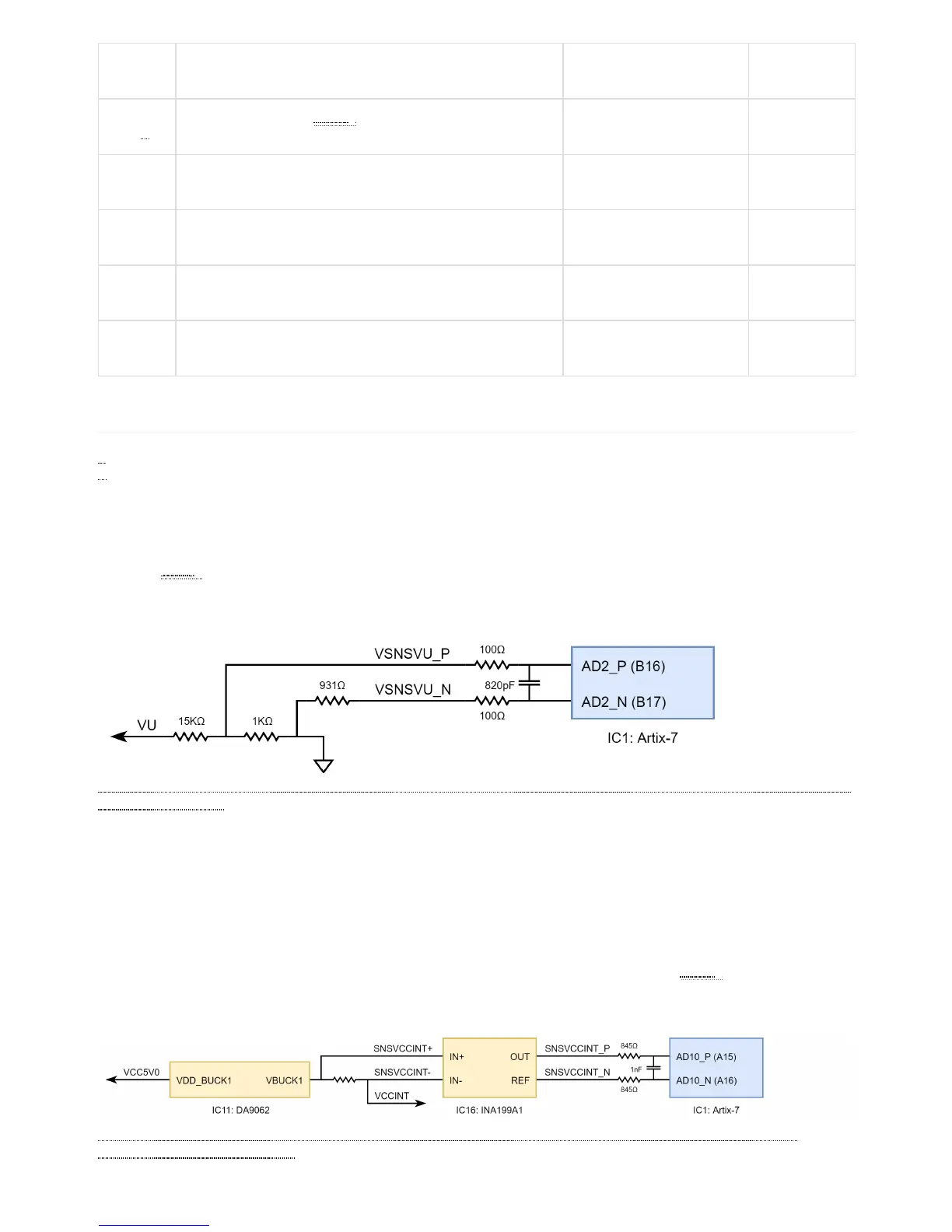
The Arty A7 includes circuitry for monitoring the voltage of an external supply connected to Power Jack J13 or an external battery pack
connected to Header J7. A voltage divider is used to scale the unregulated input voltage, VU, to be within the range (0-1V) that the on-
chip 12-bit ADC () is capable of measuring. The unregulated input voltage, VU, is divided by 16 and then fed into Auxiliary Channel 2 on
the XADC of the Artix-7. Applications that wish to monitor the voltage of an external supply may configure Channel 2 of the XADC as
a unipolar input and perform a conversion to receive a digital value corresponding to the input voltage. Figure 3.1.1 provides an overview
of the circuitry that allows an external supply voltage to be monitored.
(https://reference.digilentinc.com/_detail/reference/programmable-logic/arty-a7/arty-a7-vu-mon.png?id=reference%3Aprogrammable-logic%3Aarty-
a7%3Areference-manual)
Figure 3.1.1 Monitoring External Supply Voltage
The Arty A7 includes circuitry for monitoring the current consumed by the FPGA core. The current is monitored by measuring the
voltage across a 10 milliohm sense resistor that’s placed between the output of the DC-DC converter system (IC11, Channel 1) and the
VCCINT network. A current sense amplifier (IC16, Texas Instruments INA199A1) connected across the sense resistor provides a gain
of 50 and produces an output voltage of 500 millivolts per amp of current. Currents above 2 Amps will not damage the circuit or the
FPGA, but will be reported as 2 Amps. The output of the current sense amplifier is fed into Auxiliary Channel 10 on the XADC of the
Artix-7 FPGA. Applications that wish to monitor the current consumption of the FPGA Core and Block RAM () may configure Channel
10 of the XADC as a unipolar input and perform a conversion to receive a digital value that corresponds to the amplified sense resistor
voltage. This current sense circuit is capable of measuring current between 0 and 2 Amps. Figure 3.2.1 provides an overview of the
circuitry that allows the FPGA Core Supply current to be monitored.
(https://reference.digilentinc.com/_detail/reference/programmable-logic/arty-a7/arty-a7-vccint-mon.png?id=reference%3Aprogrammable-
logic%3Aarty-a7%3Areference-manual)
Figure 3.2.1 FPGA Core Supply Current Monitoring