Do you have a question about the Xilinx SmartLynq Plus and is the answer not in the manual?
The SmartLynq+ Module provides several key features for debug and trace operations.
Explains the SmartLynq+ Module's high-bandwidth connectivity for system debug and trace.
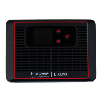
Describes the physical enclosure of the SmartLynq+ module and its heat sink assembly.
Details the DC power, USB 3.0, and Ethernet connectors located on the left side.
Describes the GPIO, JTAG, HSDP, and MICTOR connectors on the right side of the module.
Details the reset pin, mode selector switch, and micro-SD card slot on the front panel.
Lists the supported operating systems and processor architectures for host systems.
Specifies the default IP address (10.0.0.2) for the SmartLynq+ Module's USB 3.0 interface.
Step-by-step guide to associate the RNDIS driver with the SmartLynq+ Module on Windows.
Instructions for configuring the network interface on Linux using ifconfig command.
Procedure to modify the default USB 3.0 IP address using a network configuration file.
Steps to configure static IP addresses for the Ethernet connection via SSH.
Details connector dimensions, signal assignments, and pin descriptions for JTAG.
Describes the 2x6 GPIO connector, pinout, and power requirements for 8-bit operations.
Details the USB-C receptacle connector, its pins, and the HSDP interface implementation.
Covers electrical requirements for high-speed differential pairs used in HSDP.
Explains how CC lines detect orientation and power sense for USB-C cable connection.
References for VCK190 schematics and guidelines for 10 Gb/s HSDP connectivity.
Details the function, direction, and pull-up/down configurations for MICTOR connector pins.
Provides links to Xilinx support resources like Answers, Documentation, Downloads, and Forums.
Information on using DocNav and Design Hubs to access Xilinx documents, videos, and resources.
Lists supplemental material and documents useful for understanding this guide.
| Target Interface | JTAG |
|---|---|
| Storage Temperature | -20°C to 70°C |
| Host Interface | USB 2.0 |
| Status Indicators | LED |
| Supported Devices | Xilinx FPGAs and SoCs |
| Compatibility | Windows, Linux |
| Interface | USB |