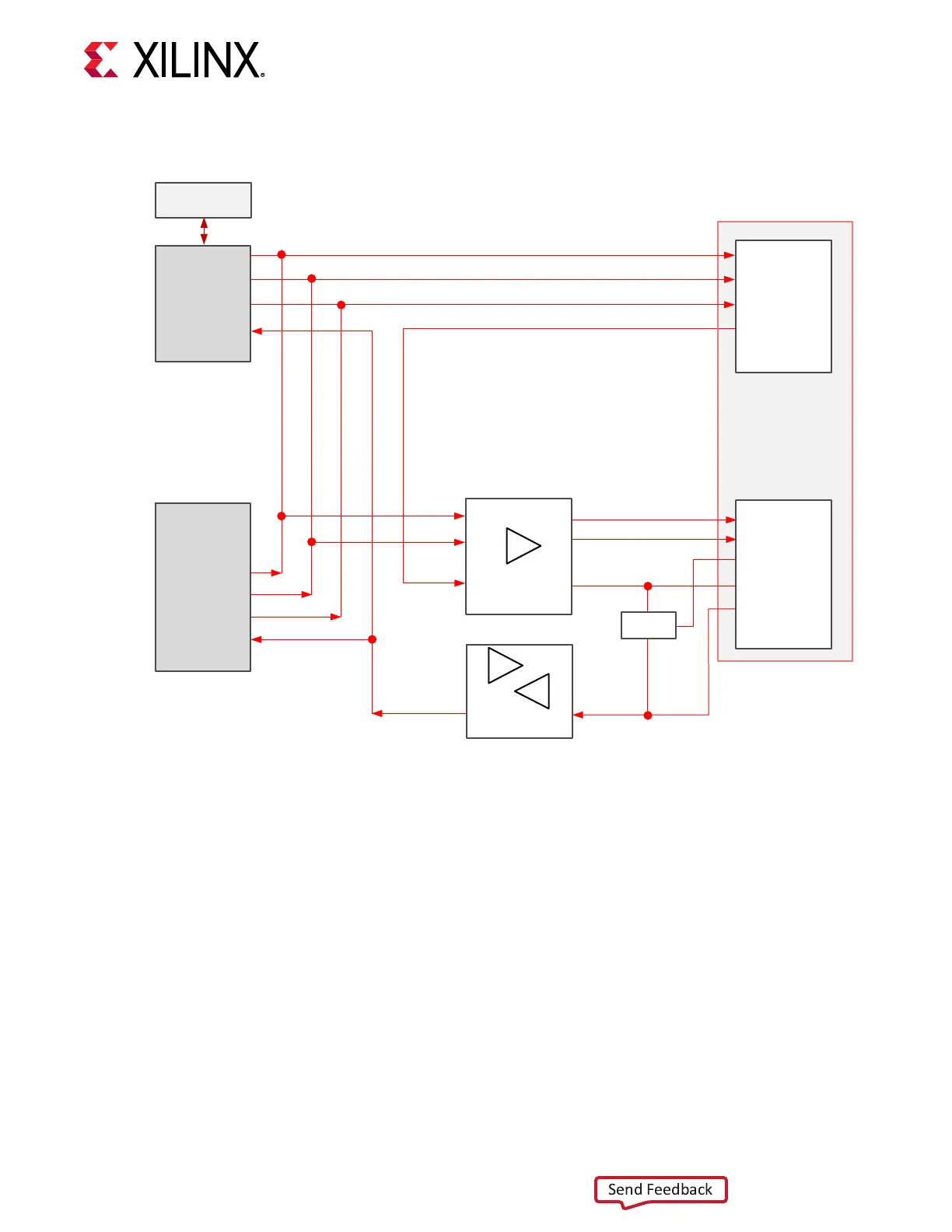
Figure 6: SP701 JTAG Chain
USB Conn
FT4232H
16
17
19
TCK>
TDI<
TMS>
PC4 14pin(2X7)
6
10
8
4
TCK>
TDI>
TDO<
TMS>
14
2
VREF
SRST
FPGA 7S100
>TCK
>TDI
<TDO
>TMS
18
TDO>
FPGA_TDI_0
FPGA_TDO_0
PC4_JTAG_TDO
FPGA_TMS_0
FPGA_TCK_0
FMC_TDO
FMC_TDI_FPGA_TDO
JTAG Devices
FMC_TMS_BUF
FMC_TCK_BUF
SN74AVC1T45
J5
TXB0304
U6
J3
U1
U5
U44
>TCK
>TDI
<TDO
>TMS
D29
D30
D31
D33
<PRSNT_L
H2
J21
SW
U42
FMC LPC
X22789-042619
FMC LPC Connector JTAG Bypass
When an FPGA mezzanine card (FMC) is aached to J21, it is automacally added to the JTAG
chain through an electronically controlled single-pole single-throw (SPST) switch, U42. The SPST
switch is normally closed and transions to an open state when an FMC is aached. Switch U42
adds an aached FMC to the JTAG chain as determined by the FMC_PRSNT_M2C_L signal. The
aached FMC card must implement a TDI-to-TDO connecon using a device or bypass jumper
to ensure that the JTAG chain connects to the U1 XC7S100 FPGA.
The U5 TXBN0304 translator between the U6 FTDI JTAG/UART interface and the J3 JTAG pod
at cable connector J3 is normally not enabled (2-pin U5 enable header J38 jumper o) as the
USB JTAG funcon using USB connector J5 is typically in use. To use the J3 JTAG pod at cable
connector, remove the J5 USB cable and install a jumper on 2-pin header J38.
Chapter 3: Board Component Descriptions
UG1319 (v1.0) July 12, 2019 www.xilinx.com
SP701 Board User Guide 20