Encoder feedback signal /A+, /A-, /B+, /B-
Calculate the electronic gear ratio
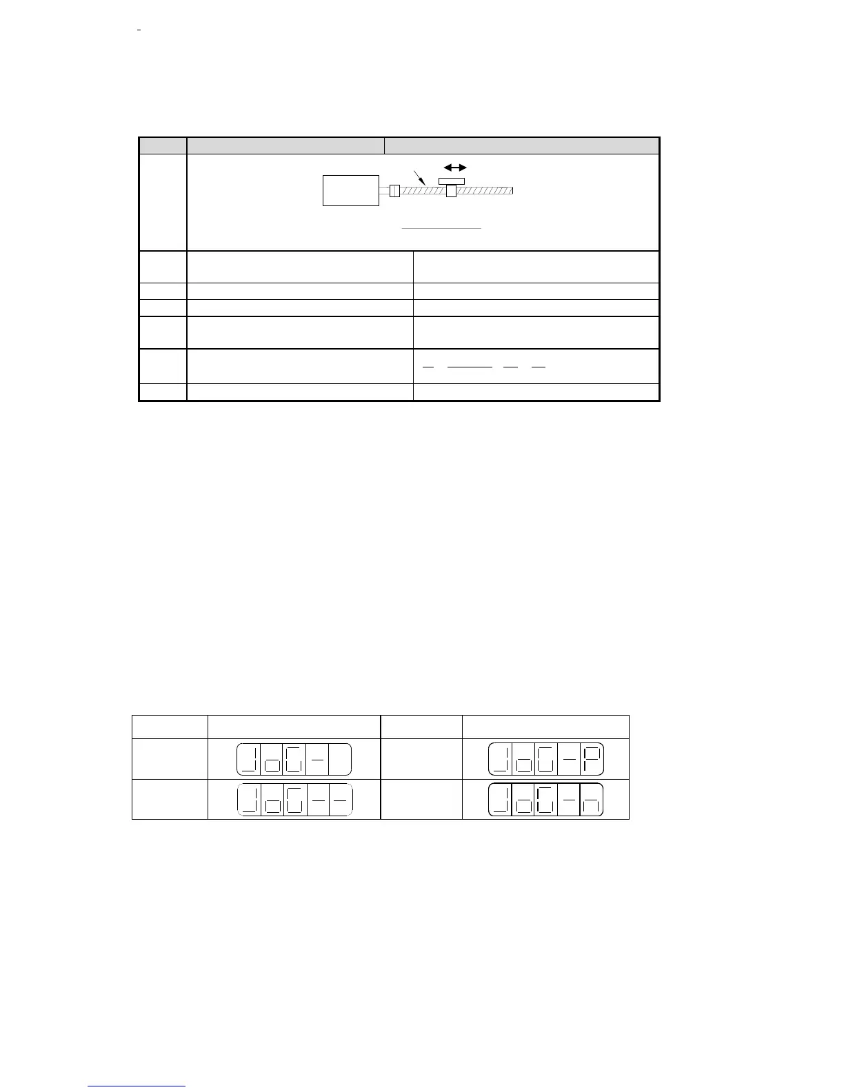
Confirm the mechanical specification
Confirm the encoder pulse number
Calculate the motion value of load
shaft rotate 1 circle
Calculate the electronic gear ratio
B 2500 4 40 80
A 5000 1 1
Parameter setting
Running mode: P0-01=6
Pulse command state: P2-00=2
Electronic gear ratio: P2-02=80 P2-03=1
Forward torque limit: P4-02=150
Reverse torque limit: P4-03=150
Positioning finished width: P5-00=7
/S-ON: P5-10=0010
/CLR: P5-24=0001
/COIN: P5-28=0001
/CLT: P5-32=0002, P5-37=0000
Debug
1. Initial debug
(a) Connect the cables correctly. Connect U, V, W, PE one-to-one, don’t cross them.
(b) open-loop test-running: power on, set F1-01=1, check if the motor can work normally. If yes, enter
F1-00. If not, check the cables.
(c) Jog test-running: enter F1-00. Press ENTER to enable the motor. Press INC for forward jog, press
DEC for reverse jog. Press STATUS/ESC to quit the jog running.
4 states when jogging:
(d) Current check offset auto-adjustment
Enter F1-02, it shows rEF.
Press ENTER, it shows rEF and flickers.
After 5s the auto-adjustment finished, it shows donE.
Press STATUS/ESC to exit.
2. Debug the motor with machine
(a) Check the motor rotation direction, if it is reverse from the actual needs, set F1-05 to 0 (servo force
OFF). Then set P0-05 to 1, re-power on the servo.
(b) Check the servo stability and response, adjust the servo gain.
3. Debug with PLC program.
 Loading...

