Do you have a question about the Xinje DS3 series servo and is the answer not in the manual?
Essential safety guidelines for handling and operating the servo drive and motor.
Procedures to confirm product completeness and condition upon arrival.
Explains the DS3 series servo drive model nomenclature and its parameters.
Details the servo motor model structure and the meaning of its various codes.
Visual guide to the servo motor's external components and their functions.
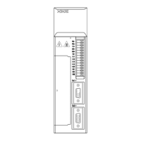
Explains the front panel elements of the servo drive, including LEDs, display, and connectors.
Covers motor storage, mounting environment, concentricity, and cable handling.
Specifies installation location, ambient conditions, and orientation for the servo drive.
Provides installation dimensions and required clearances for the servo drive in a cabinet.
Shows installation dimensions for servo motors, including mounting hole patterns.
Describes the main circuit terminals for power, motor, and braking resistor connections.
Details servo motor winding connections and the CN1 terminal assignments for I/O signals.
Explains input/output signal types and the CN2 encoder connector pinout.
Describes COM1 (RS232) and COM2 (RS232/RS485) communication ports and their parameters.
Provides illustrative diagrams for common servo drive and motor connection setups.
Illustrates detailed wiring for speed, torque, position commands, and enable signals.
Explains how to use the buttons (STATUS/ESC, INC, DEC, ENTER) to navigate states and set parameters.
Describes the different states displayed on the panel: running, monitoring, auxiliary, parameter setting, alarm.
Explains the LED bit data displayed for speed and torque control modes, like S-ON, V-CMP, CLT.
Details the bit data displayed for position control modes, such as COIN, NEAR, and TGON.
Guides users on how to select and view monitoring codes (U-XXX) for system status.
Lists available monitoring codes (U-000 to U-021) and their corresponding measured values.
Explains how to interpret I/O signal states using LED indicators on the operation panel.
Introduces auxiliary function codes (F0-** to F5-00) for system info, alarms, and settings.
Details how to view system info (F0-XX) and change the motor type compatibility.
Explains how to use the jog mode (F1-00) for manual motor movement and testing.
Covers test run, offset auto-adjustments (current, speed, torque), and forced functions.
Describes how to access and view alarm codes and related information.
Lists alarm codes (F3-XX), their reasons, and suggested solutions for troubleshooting.
Explains how to perform a factory reset (F4-00) and enable external PC monitoring (F5-00).
Step-by-step guide on how to change parameter values using the operation panel, e.g., P3-09.
Explains how system and panel errors are displayed and how to reset them.
Configures main operating modes, sub modes, and serial port settings.
Sets rotation direction and defines stop modes for alarming or servo OFF conditions.
Adjusts speed loop gain, integral time, and feed-forward parameters for precise speed control.
Configures pulse input modes, electronic gear ratio, and filter settings for positioning.
Sets analog speed values, internal speeds, JOG speed, and max speed limits.
Configures analog torque values, torque limits, and internal speed limits during torque control.
Sets positioning width, zero clamp, rotation checking speeds, and speed signal widths.
Configures servo OFF delay time, brake command output, and wait times.
Assigns various input signals (S-ON, P-CON, etc.) and configures mode selection logic.
Configures output signals like positioning end, speed consistent checking, and ready signals.
Lists alarm codes (E-001 to E-017), their explanations, reasons, and solutions.
Provides detailed reasons and solutions for common alarms like over current, over speed, and encoder errors.
Explains current offset auto-adjustment and servo enable signal configuration.
Details how to set up external pulse control for servo positioning using PLC signals.
Explains wiring for pulse modes and how to calculate electronic gear ratios.
Guides on setting up segment speed control using input signals like SPD-D, SPD-A, SPD-B.
Describes how the servo drive seamlessly switches between different operating modes.
Details the configuration for the C-SEL signal to manage mode switching and selection.
| Communication | RS485, CANopen |
|---|---|
| Control Mode | Position control, Speed control, Torque control |
| Encoder Type | Incremental encoder |
| Protection Functions | Overcurrent, Overvoltage, Undervoltage, Overload, Encoder fault |
| Rated Power | 0.1kW to 7.5kW (depending on model) |
| Series | DS3 series |