DS3 series servo manual
10
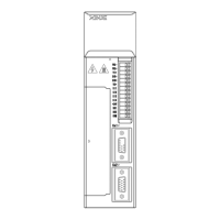
2. Servo motor winding connector terminals
Signal Motor terminal
80 series 110, 130 series
PE 4 1
U 1 2
V 3 3
W 2 4
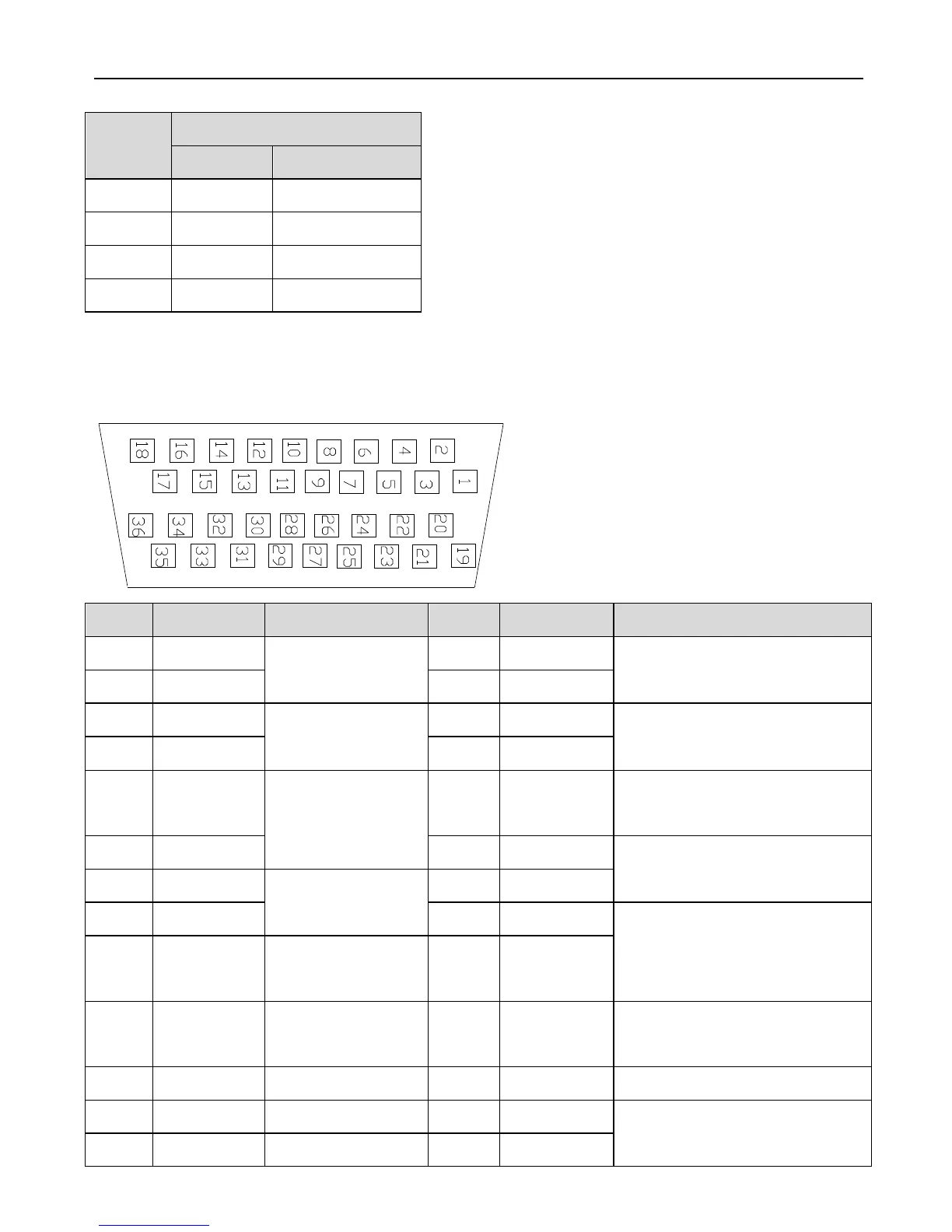
3. CN1 terminal arrangement
Look at the solder side:
No. Terminal Explanation No. Terminal Explanation
1 GND Z phase
transistor output
19 V-REF Analog set, speed
2 CZ 20 GND
3 SO3- Output terminal
3
21 T-REF Analog set, torque
4 SO3+ 22 GND
5 SO2- Output terminal
2
23 PL1 Power supply for open
collector
6 SO2+ 24 PULS- Input pulse A (pulse signal)
7 SO1- Output terminal
1
25 PULS+
8 SO1+ 26 SIGN- Input pulse B (pulse
direction)
9 +24V +24V for input
terminal
27 SIGN +
10 SI7 Input terminal 7 28 PL2 Power supply for open
collector command
11 SI6 Input terminal 6 29 NC Vacant
12 SI5 Input terminal 5 30 ZO+ Z phase differential output
13 SI4 Input terminal 4 31 ZO-

 Loading...