DS3 series servo manual
37
Wiring:
(a) “pulse + direction” signal: “pulse” connects CN1-24/CN1-25, “direction” connects
CN1-26/CN1-27.
(b) “AB-phase” signal: A-phase connects CN1-24/CN1-25, B-phase connects
CN1-26/CN1-27.
(c) The shield layer connects to COM terminal of PLC.
The details please refer to DS series servo manual
Parameters:
Calculate the electronic gear ratio:
15000 × gear ratio = 1.75 × pulse quantity per rotation of servo motor
Pulse quantity per rotation of servo motor = 2500 × 4 = 10000, so gear ratio = 7/6.
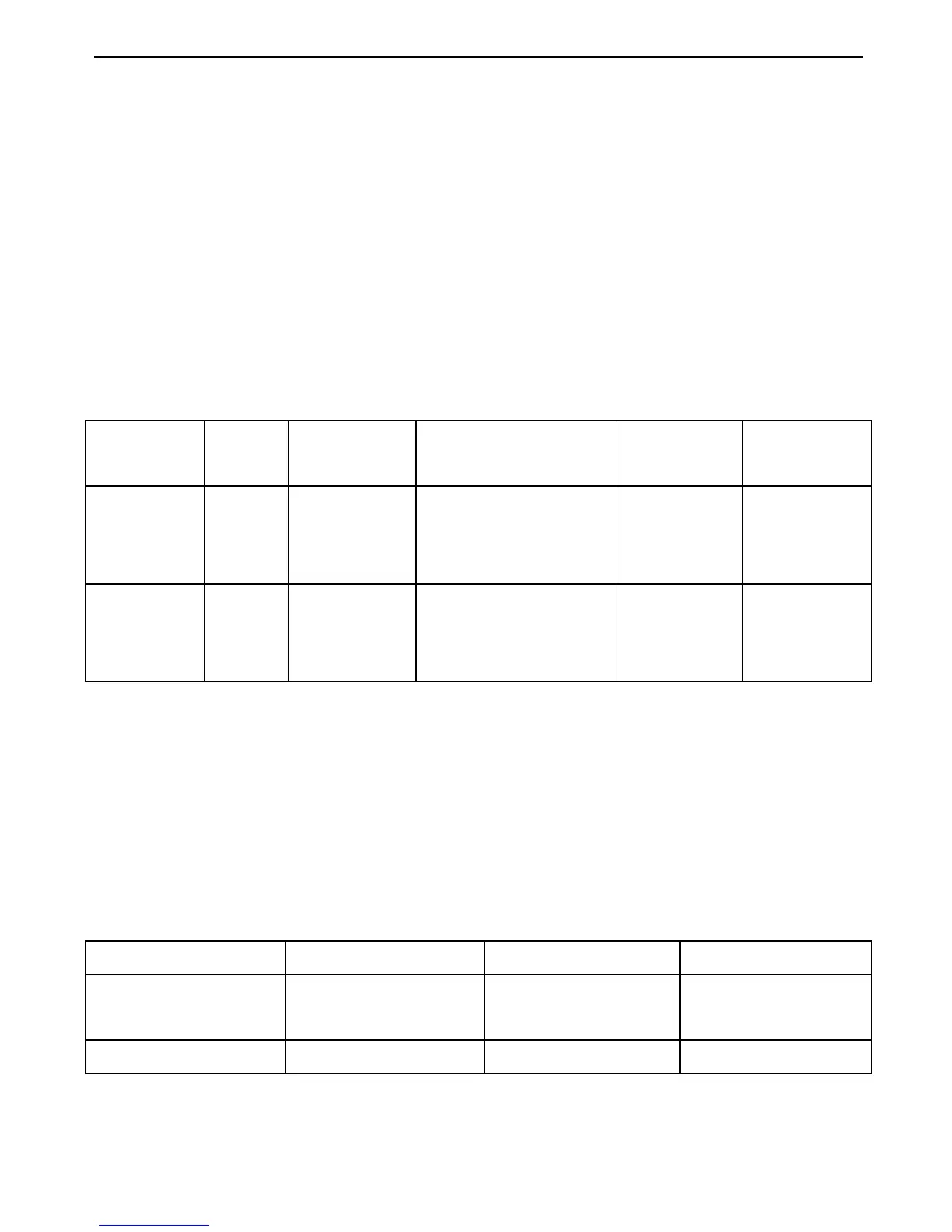
Parameter
code
P0-00 P0-01/P0-02 P2-00 P2-02 P2-03
Explanatio
n
Main
mode
Sub mode Pulse mode Numerator
of electronic
gear ratio
Denominator
of electronic
gear ratio
Setting
value
(HEX)
0 6 “AB phase” signal: 1
“pulse+direction”
signal: 2
7 6
(2) Segment speed control (internal setting speed)
For example: SPD-D, SPD-A, SPD-B connects to SI2, SI6, and SI7 separately which are all
positive signal input, uses software filter. Three segments of speed are 100rpm, 500 rpm,
1500 rpm, soft start acceleration/deceleration time is 200ms.
Wiring:
SPD-D connects to CN1-16, SPD-A connects to CN1-11, SPD-B connects to CN1-10,
external 24V power supply connects to CN1-9.
Terminal parameter setting:
Parameter code P5-10 P5-14 P5-15
Explanation Enables to change
terminal distribution
SPD-A、SPD-D
SPD-B
Setting value (HEX) XX01 0602 XX07

 Loading...