Do you have a question about the Xinje DS2-20P4-AS and is the answer not in the manual?
Procedure for checking products upon delivery.
General precautions for servomotor and servo drive installation.
Safety guidelines for wiring the servo drive and motor.
Safety measures to follow during operation.
Checklist for verifying received servo drive and motor.
Guidelines for installing the servomotor correctly.
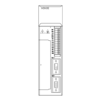
Guidelines for installing the servo drive.
Essential instructions for connecting the main power circuit.
Specifics of main circuit terminals for different drive models.
Continues detailing main circuit terminal configurations.
Details the function of CN0, CN1, and CN2 connectors.
Pin assignments for the CN1 (DB15) connector.
Details the pinout for the CN2 encoder connector.
Wiring for RS-232 and RS-485 communication ports.
Explains input terminals for pulse signals.
Details on configuring SI input signals.
Circuit diagrams for analog signal inputs.
Describes optocoupler and relay output signals.
Wiring diagram for encoder feedback signals.
Provides wiring examples for common configurations.
Example wiring for position control mode setup.
Introduction to the operate panel's functions and modes.
Jog and trial operation functions under F1-XX.
Procedure for setting the correct motor type.
How to view and interpret alarm codes.
Steps to restore factory default parameter settings.
Overview of available control modes and submodes.
Key parameters for fundamental servo operation.
Enabling servo power and motor operation.
Configuring stop behavior when overtravel signals are active.
Using and configuring overtravel limit inputs.
How the power-off brake works and is wired.
Mechanism to limit the maximum output torque.
Operating the servo using external pulse commands.
Explanation of pulse command signal formats.
How to calculate and set the electronic gear ratio.
Operating the servo using internal position commands.
Configuring parameters for internal position control.
Parameters for setting up position segments 1 through 16.
Procedure for finding and setting the reference origin.
Detailed diagrams and steps for finding the reference origin.
Controlling servo speed using analog voltage signals.
Configuring the voltage input for rated speed.
How the zero clamp function operates and is configured.
Parameters and signals for limiting motor torque.
Setting maximum output torque limits internally.
Setting external torque limits using input signals.
Controlling servo speed using internal preset values.
Controlling servo speed using pulse frequency signals.
Controlling servo torque using analog voltage signals.
Controlling servo torque using internal preset values.
| Brand | Xinje |
|---|---|
| Model | DS2-20P4-AS |
| Category | Servo Drives |
| Language | English |