27
U-21 displays I/O signals status
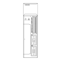
The following diagram describes the input and output signals status displayed in U-21.
Diagram 1 Diagram 2
In diagram 1, LED4 and LED5 stand for input signals status, and LED1 and LED2 stand
for output signals status. In diagram 2 there shows the segment No. of each LED.
Input signals status
/SPD-A internal set speed selection
/SPD-B internal set speed selection
/P-CON proportion action command
/C-SEL control mode selection
/INHIBIT prohibit pulse command
/P-CL external torque limit at
forward side
/N-CL external torque limit at
reverse side
/SPD-D internal set speed selection
/COIN positioning completed
/V-CMP speed synchronization
checking
/Z encoder Z phase output
/VLT speed limit checking
U-22 displays I/O terminals status
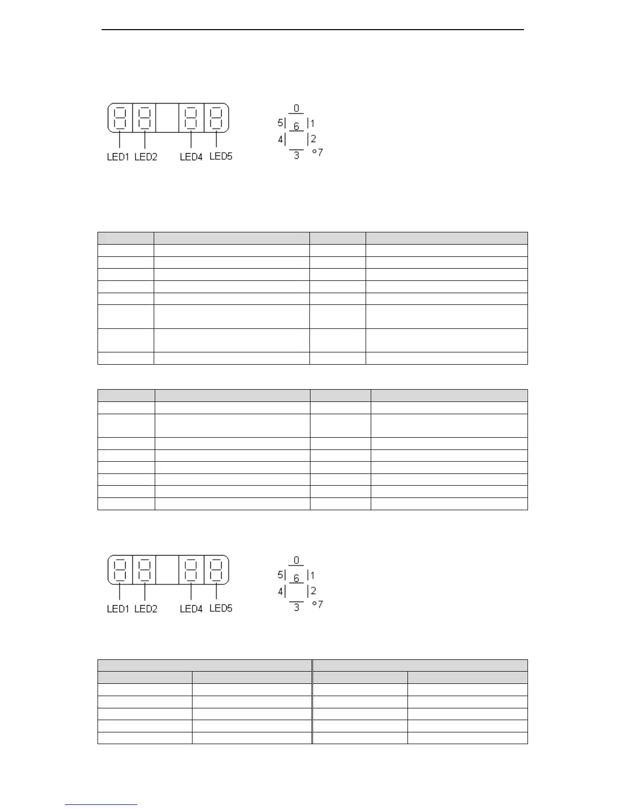
The following diagram describes the input and output terminals status:
Diagram 1 Diagram 2
In diagram 1, LED5 stands for input signals status, and LED2 stands for output signals
status. In diagram 2 there shows the segment No. of each LED.
 Loading...