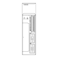
EasyManua.ls Logo

Xinje DS3 Series - SI input signal; SO output signal

Xinje DS3 Series
120 pages
To Next Page IconTo Next Page
To Previous Page IconTo Previous Page
Loading...
39
PLC, SCM, etc. servo drive
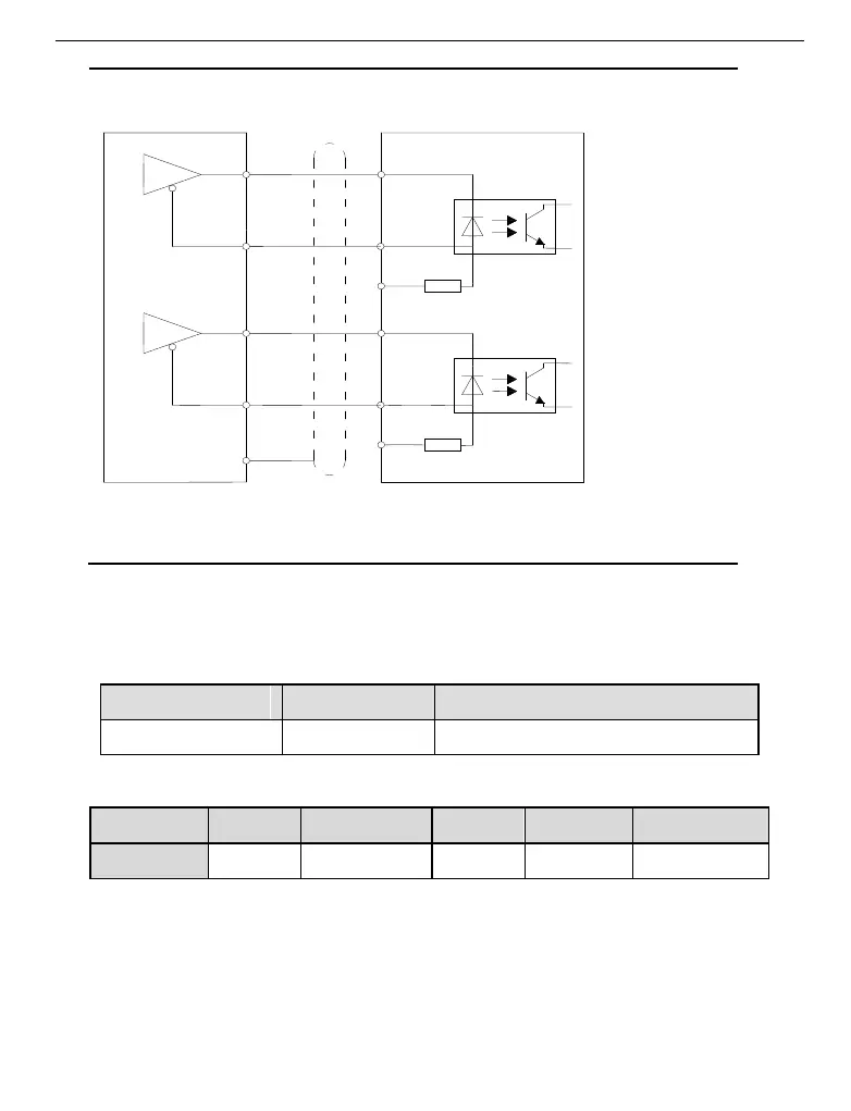
When upper device is 5V differential output, please use this wiring diagram.
Please note: P+24V and D+24V must be vacant.
SI input signal
Please use relay or open collector transistor to connect. When using relay, please choose
micro-current relay. Otherwise, the contact will be not good.
Type
Input terminal
Function
Digital input
SI1~SI5
Multi-functional input
Default setting of SI input terminal
Terminal
SI1
SI2
SI3
SI4
SI5
Function
/S-ON
/ALM-RST
/P-OT
/N-OT
Not distribute
P+24V
PUL+
PUL-
P-
R=3.3K
DIR-
D-
R=3.3K
P+5V
D+5V
Shield layer
0V
D+24V
DIR+

Other manuals for Xinje DS3 Series

Related product manuals