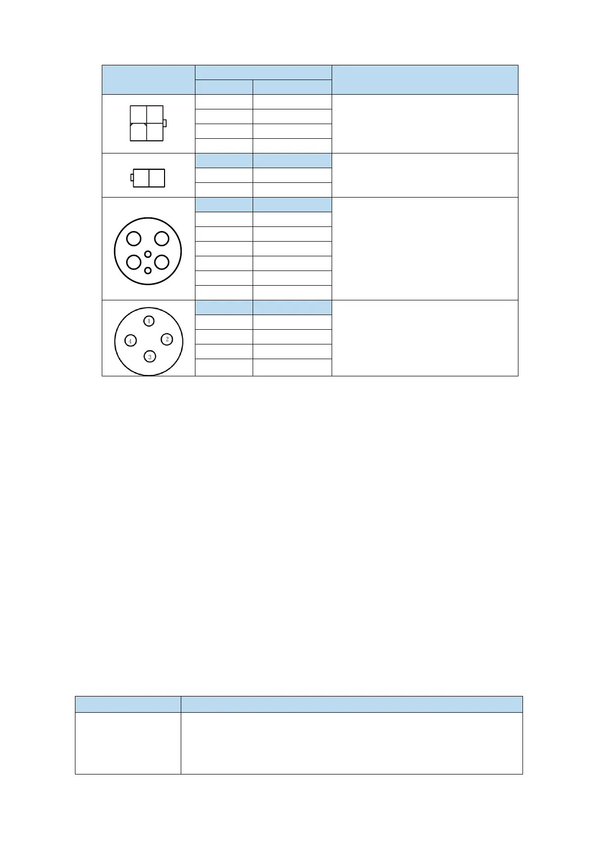
(2) Power cable connection on motor side
Match MS5-S02 small aviation plug
motor
Match MS5G series 130 flange 850W
non-brake motor
Brake pins:
The cable including pin BK+, BK- is used for the brake motor. The cable of the non-brake motor has
no BK pins.
1.4 Selection of other accessories
1.4.1 Selection of regenerative resistance
When the servo motor is driven by the generator mode, the power returns to the servo amplifier side,
which is called regenerative power. The regenerated power is absorbed by charging the smooth
capacitor of the servo amplifier. After exceeding the rechargeable energy, the regenerative resistance is
used to consume the regenerative power.
The servo motor driven by regenerative (generator) mode is as follows:
The deceleration stop period during acceleration and deceleration operation;
Running vertically and axially;
When the external load drives the motor to rotate.
Regenerative resistance connection terminals
(1) Using built-in regenerative resistance, short P + and D terminals, P + and
C are disconnected.
(2) Use external regenerative resistance, connect regenerative resistance to P
+ and C terminals, remove P + and D short wiring, P0-25 = power value,
P0-26 = resistance value.

 Loading...