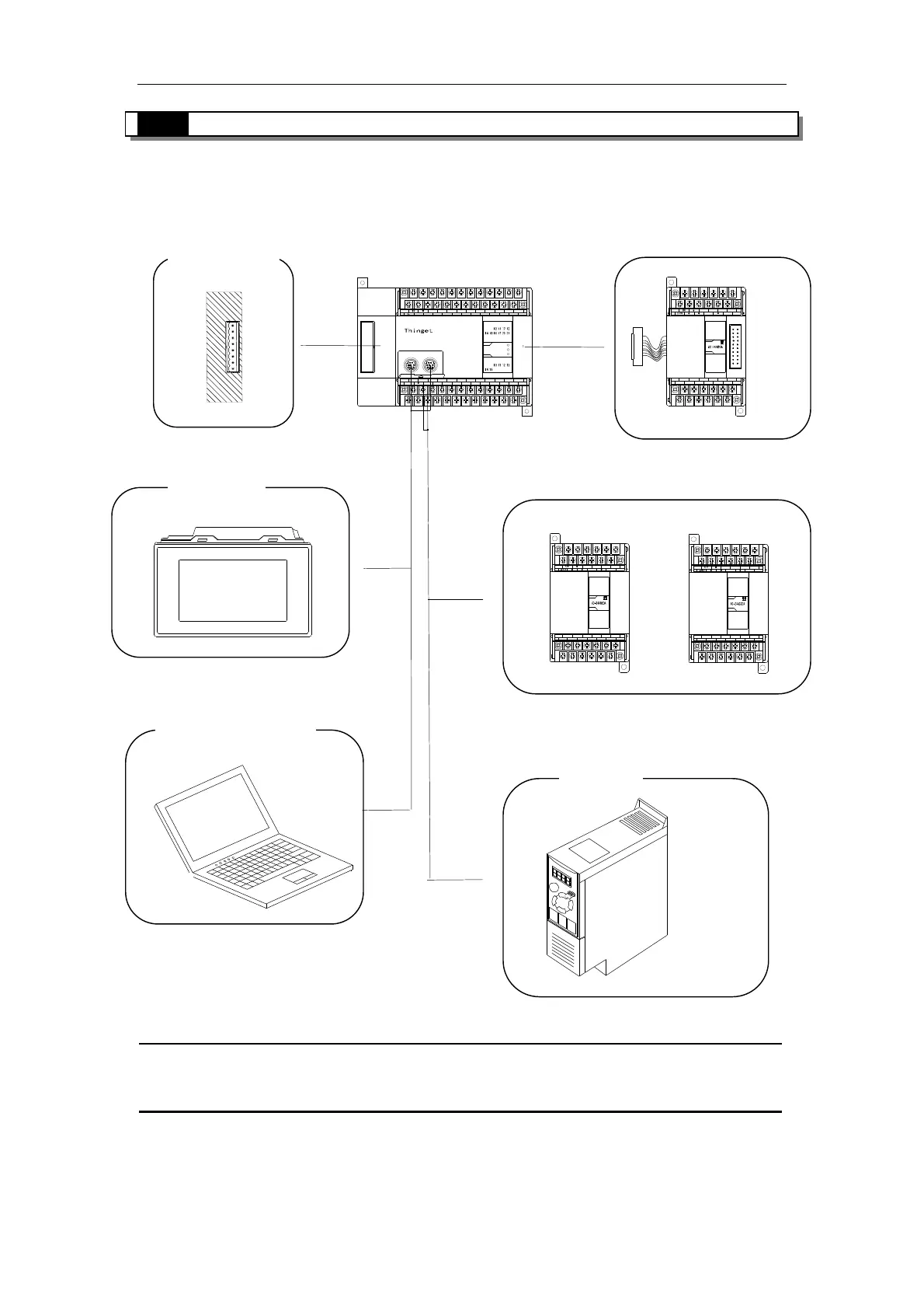
3-1.System Structure
In the below Graph, we show the common system structure according to XC series PLC basic
configuration. Via this graph, we could know the basic connection among PLC and peripheral
equipments; also classic applications of PLC's each COM port, connection and expansion etc.
FG
COM
COM X0
X1
X2
X3
X4
X5
X6
X7 X15
X16X14
X13
X12
X11
X10
X17
X20
X21
PWR
Y
X
PORT1 PORT2
Y15
Y14
Y13
Y12COM3
Y5
Y7
Y6
Y11
COM4Y10
Y4
Y3COM2
Y2
COM1
Y1
COM0
Y0
A
B
24V
0V
10 4532
RUN
ERR
XC3-32R-E
67
76
23 5401
AO1
AO0
VO0 VO1
C1C0
VI3
AI3
C0
VI0 AI1
AI0 VI1 C2 AI2
C3VI2C1
PWR
AI
AO
AO1
AO0
VO0 VO1
C1C0
VI3
AI3
C0
VI0 AI1
AI0
VI1 C2
AI2
C3
VI2C1
PWR
AI
AO
AO
AI
PWR
C1 VI2 C3
AI2C2VI1
AI0
AI1VI0
C0
AI3
VI3
C0 C1
VO1VO0
AO0 AO1
※1:In the above graph, the communication devices connected to the COM port are only samples for your
reference. Each COM port can connect with many devices in real applications.
HMI
Expansion
Inverter
Network Module
Program Software
CPU Unit
BD Card
 Loading...