Appendix 2 instructions list
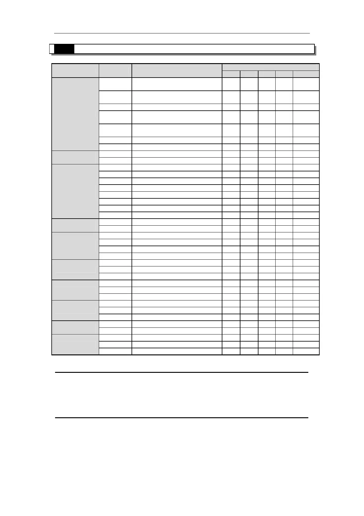
Appendix 2-3.Special Instructions List
Suitable type
Sort Mnemonic
Function
XC1
XC2
XC3
XC5
XCM
PLSY
1※
Single segment no
accelerate/decelerate pulse output
√ √ √ √
PLSR
1※
Relative position multi-segment pulse
control
√ √ √ √
PLSF
1※
Changeable frequency pulse output √ √ √ √
PLSA
1※
Absolute position multi-segment
pulse control
√ √ √ √
PLSNEXT/
PLSNT
change the pulse segment √ √ √ √
PLSMV
2※
Save the pulse number in the register
√ √ √ √
pulse
STOP Pulse stop √ √ √ √
HSCR
2※
Read high speed counter value √ √ √ √
High Speed
Counter (HSC)
HSCW
2※
Write high speed counter value √ √ √ √
COLR MODBUS coil read √ √ √ √
INPR MODBUS input coil read √ √ √ √
COLW MODBUS single coil write √ √ √ √
MCLW MODBUS multi coil write √ √ √ √
REGR MODBUS register read √ √ √ √
INRR MODBUS input register write √ √ √ √
REGW MODBUS single register write √ √ √ √
MODBUS
communication
MRGW MODBUS multi register write √ √ √ √
SEND Free format data send √ √ √ √
Free format
communication
RCV Free format data receive √ √ √ √
CCOLR CANBUS coil read √
CCOLW CANBUS coil write √
CREGR CANBUS register read √
CANBUS
communication
CREGW CANBUS register write √
STR Precision time √ √ √ √
STRR Read precision time register √ √ √ √ Precision time
STRS Stop precision time √ √ √ √
EI Enable interruption √ √ √ √
DI Disable interruption √ √ √ √ interrupt
IRET Interruption return √ √ √ √
BSTOP Stop the block √ √ √ √
BGOON Continue running the block √ √ √ √ BLOCK
WAIT Wait √ √ √ √
FROM Read the module √ √ √ √
Read/write
expansion
TO Write the module √ √ √ √
FRQM Frequency measurement √ √ √ √
PWM Pulse width modulation √ √ √ √
others
PID PID control √ √ √ √
1※ :All the instructions are 16bits except the instructions with 1※ which has 32bits. 32bits instructions are added
D in front of its 16bits instruction. Such as ADD(16bits) / DADD(32bits).
※2: These instructions are 32bits, and have no 16bits format.
※3: √ means this series support the instruction.

 Loading...