XO 4 & XO FLEX TROUBLE SHOOTING GUIDE
Version 3.30 28
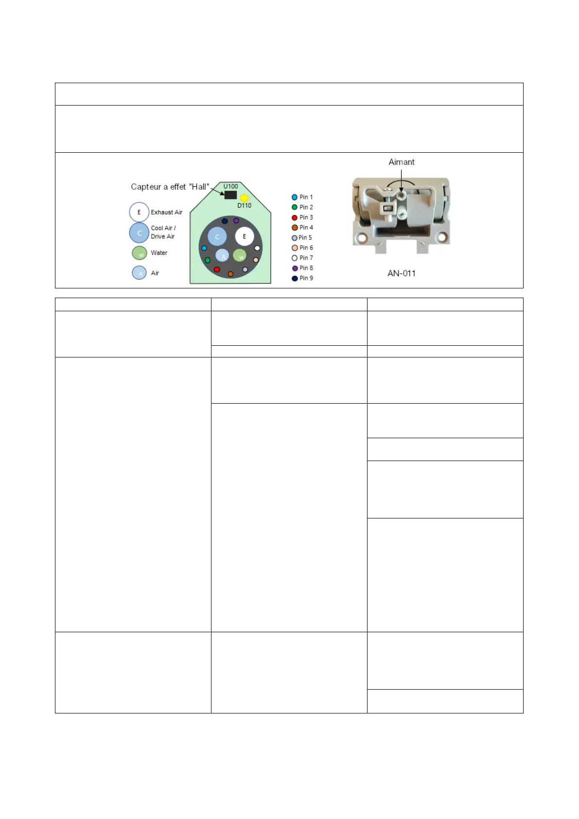
“SUSPENSION PCB”, AD-605.
Different board designs based on AO-605:
The board function provides the voltages required to operate the instruments (voltage, water and air),
supplies the voltage to the optical fibre and via the Hall effect sensor to detect if the instrument is
activated.
when the instrument is
pulled forward.
Suspension cable is not properly
mounted or is defect.
Check suspension cable is firmly
connected
Replace suspension cable.
Displayed if the instrument in
hand does not match the
suspension configuration or is
placed on the wrong connection
Before entering the technician
menu.
Verify that the instrument is
Verify that the instrument is
inserted on the correct
Verify the number behind the
connector.
In the technician menu, Verify the
configuration in the “SUSP 1-6”
and set the correct item.
Consult the “
Technician menu”
on page 26 for more information.
If the parameters described
above are correct:
Measure the 3.3V on pin 15 J2x
(J22 to J26) when the instrument
is activated. If the 3.3V is not
present, the main board "AN-
368" is defective, change it.
If the 3.3V is present it indicates
that the Suspension PCB is
Displayed if the instrument being
handled is not compatible with
the suspension PCB.
Before configuring the SPCB,
check the table “Suspension
Configuration” under “to be
selected in SPCB 1-6” to find the
Configure “SPCB 1-6” in the
technician menu.