XO 4 & XO FLEX TROUBLE SHOOTING GUIDE
Version 3.30 78
control Error” during start-
up
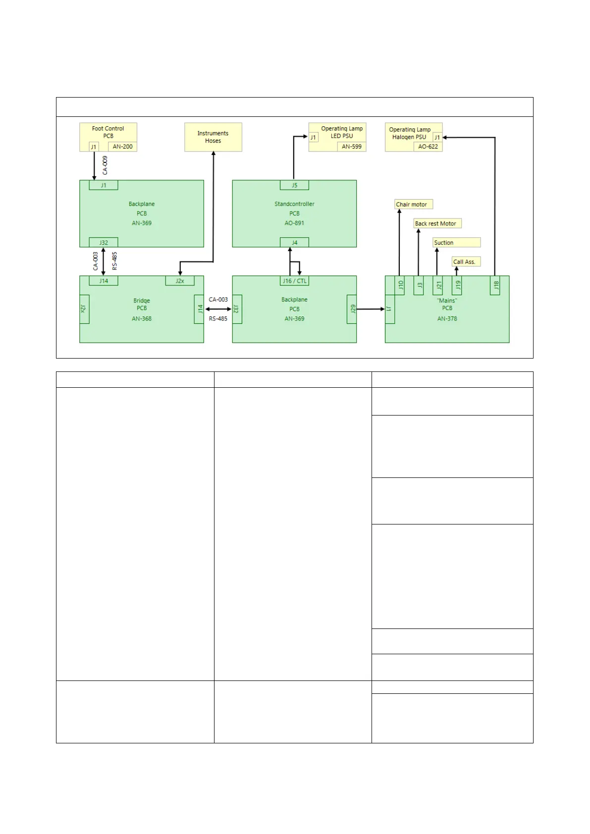
There is no BUS RS-485
communication between the foot
control and the Unit
Verify that the foot control cable
(CA-009) is not damaged.
Measure with an ohmmeter from
the Backplane J14 to the foot
control J1 pin 1 to 4, if there a
break on the cable CA-009 Value
MΩ.
Measure the resistance between
Pin 1 and 2 (RS-485
communication BUS, the value
Measure the 5V voltage between
Pin 1 (Yellow +) et Pin 4 (Green
GND).
If the +5V Voltage is missing :
- Verify the fuses on “Power
Supply AN-371”
- Read “5V Overvoltage
protection” chapter “
Power
Supply AN-371” on page 14
If all the above is correct, then the
foot control is defective.
All defective foot control must be
sent back to XO-care
Service”
Displayed after switching on the
unit if there is no communication
between the "Stand Controller"
A0-981 and the pedal.
Either due to a cable break, a
Recalibrate the foot control.
communication cable is properly
connected between J14 (bridge)
and J32 (Backplane) in the unit.