XO 4 & XO FLEX TROUBLE SHOOTING GUIDE
Version 3.30 68
SUCTION ON BRIDGE OR CHAIR
The XO units are equipped with 2 suction located either on the bridge or on the chair. Their
functionalities are identical.
The suction system works as follows: when one of the two hoses is lifted, the suction system
starts to work.
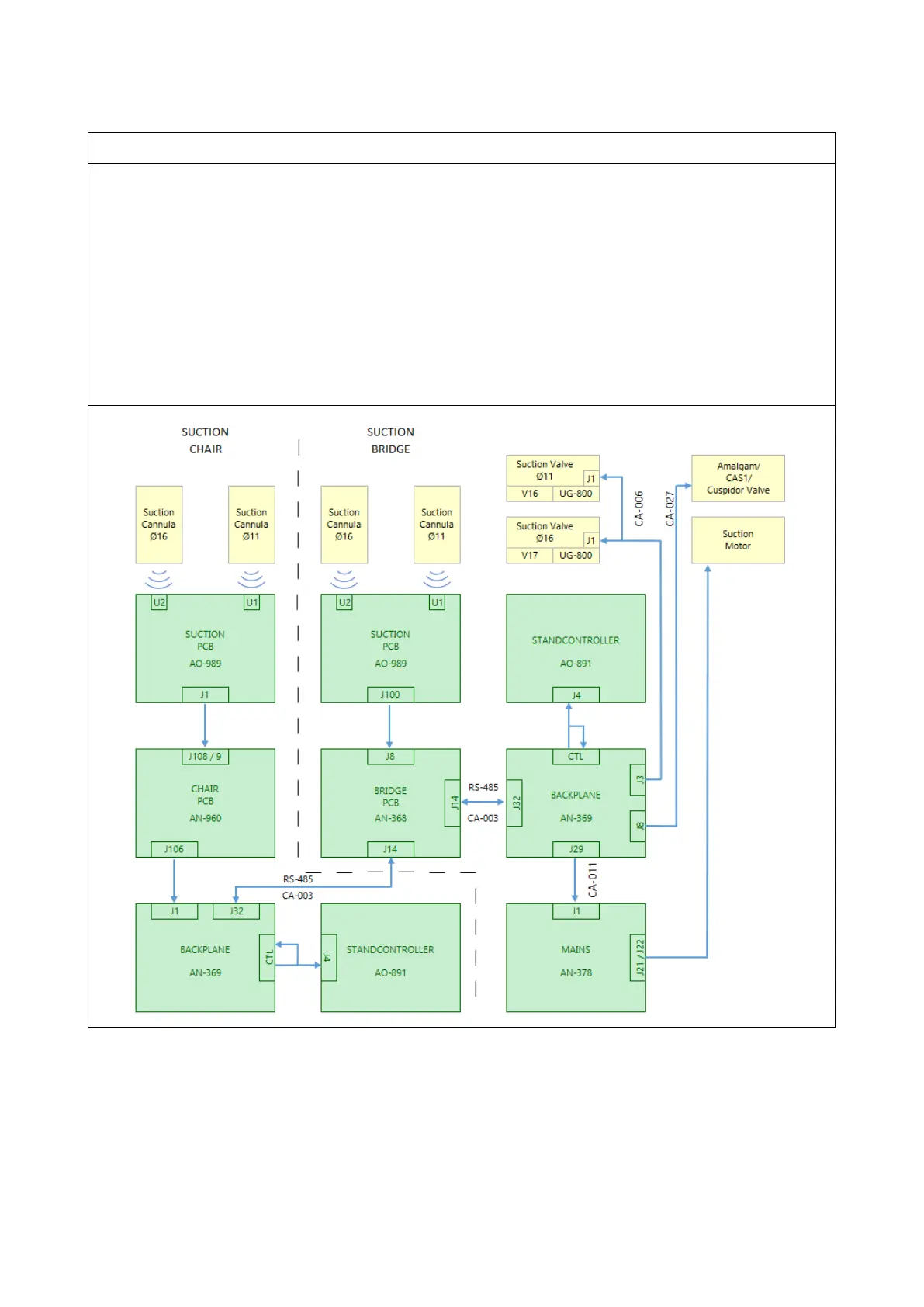
In the instrument holder, the PCB is connected directly to the “Bridge PCB AN-368” via the CA-
045 cable. On the chair, the cable is connected to the AN-369 board on J1
“Signal chair”.
The communication is as follows
When one of the hoses is activated, it sends a signal to the “Stand Controller” board which
opens valves V16 (suction hose Ø11) and/or V17 (suction hose Ø16). The “Stand Controller”
activates at the same time, CAS1 (if installed via cable CA-027) and via cable CA-011 sends a
signal to a relay that starts the suction motor J21 on “MAINS” AN-378.


 To Next Page