4
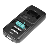
Cross Signal Pins: Holds the MCU board, MCU spare cable
or DIY signal interface.
The Cross-shaped signal pin is used to place MCU
board, MCU spare cable or DIY signal cable to read or
write MCU and ECU chips.
5
Locker: Locks the EEPROM component transponder slot to
make sure it is functioning.
6
EEPROM Component Transponder Slot: Holds the
EEPROM plug-in transponder or EEPROM socket, used to
read & write EEPROM chip.
The right-bottom corner of the slot is PIN 1. Please
check the DIP SOCKET diagram printed on the right of
the slot.
7
Status LED: Indicates current operating status.
8 IC Card Induction Area: Used to read and write IC card data.
9
Display Screen: Show remote frequency or transponder ID.
10
Remote Frequency Button: Press this button to show remote
frequency in the display screen.
11 Transponder ID Button: Press this button to show
transponder type and ID in the display screen.
12
Transponder Slot: Holds the transponder to read or write
transponder data.
13
Vehicle Key Slot: Used to hold the vehicle key to read or write
vehicle key data.