VESDA-EVES-A10-P Product Guide
36 www.xtralis.com
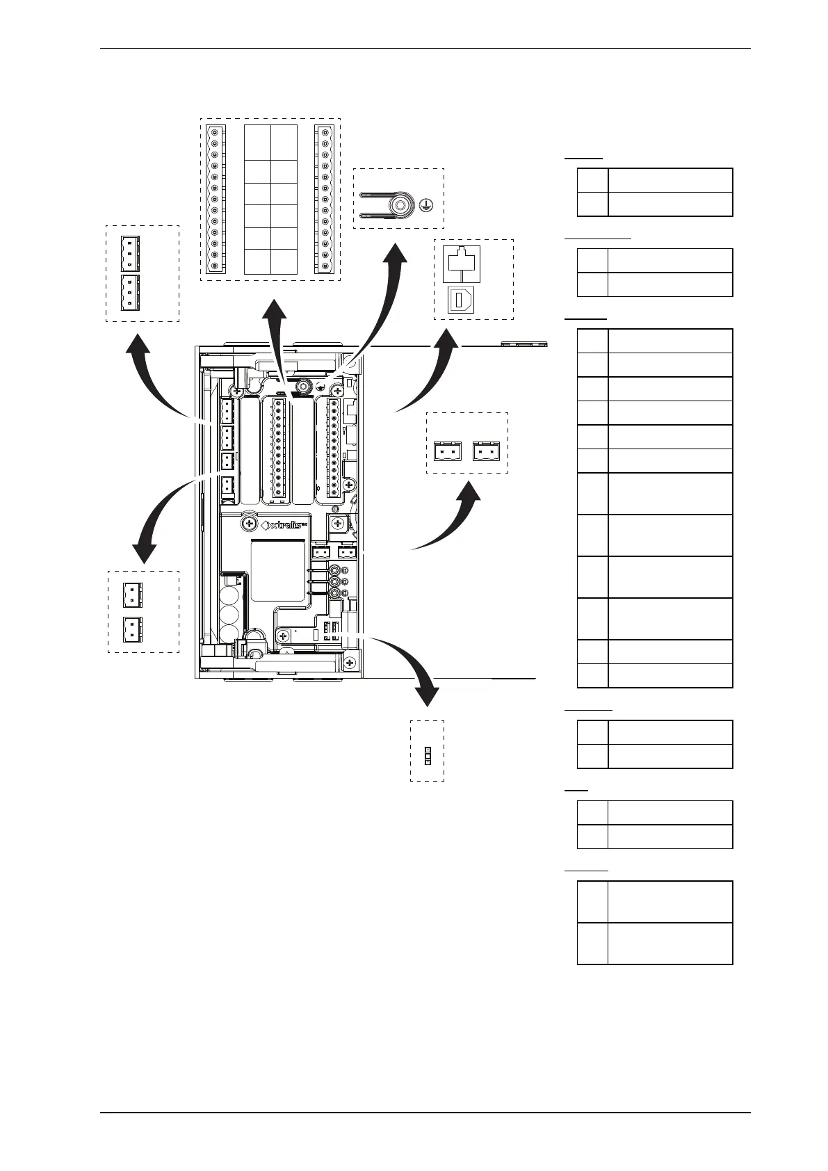
4.3.2 Socket Locations
R
S
T U
+
-
+
-
A
B
+
-
+
-
C
D
SHSH
C NO
RL7
C NO
RL5
C NO
RL4
C NO
RL2
C NO
RL1
NC C NO
RL 3 U FAULT
RL8
C NO
RL9
C NO
RL10
C NO
RL11
C NO
RL12
C NO
NC C NO
RL 6 FIRE 1
J
I
H
G
F
E
K
L
M
N
O
P
Q
V
Legend
Power
A Power Out
B Power In
VESDAnet
C VESDAnet B
D VESDAnet A
Relays
E 3 – Urgent Fault
F 1 – Disable
G 2 – Minor Fault
H 4 – Alert
I 5 – Action
J 7 – Fire 2
K 8 – First Alarm
Sector 1
L 9 – First Alarm
Sector 2
M 10- First Alarm
Sector 3
N 11 – First Alarm
Sector 4
O 12 - Scanning
P 6 – Fire 1
Comms
R Ethernet
S USB
GPI
T Monitored GPI
U Unmonitored GPI
Ground
V Jumper for ground
fault monitoring
Q Chassis Ground
Terminal
Figure4-33: Socket Locations
4.3.3 Power Source
There are two sets of power terminals on the main board (Figure4-33). Connect a 24 VDC power supply which
is compliant with local fire protection codes and standards to the PWRINsocket, and if required loop out to
another detector via the PWROUT socket.