VESDA Accessories Guide
VESDA by Xtralis
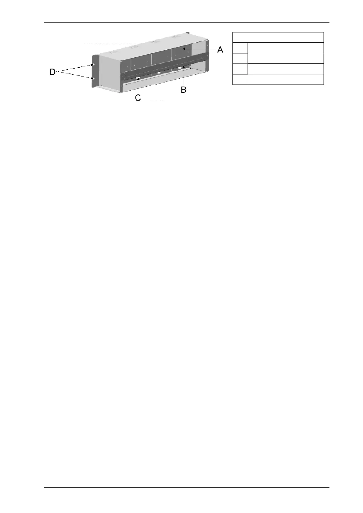
Legend
A Back Section
B Cable Tie Bar
C Cable Entry Holes
D Mounting Holes
Figure 3-4: 19” Subrack Back View
3.2.2 Mounting a 19” Subrack
The 19” Subrack is secured by bolts to a Standard 3U Subrack System. If the 19” Subrack is to be mounted
onto a wall, first fasten the optional wall mounting bracket to the wall and then install the 19”subrack onto the
wall mounting bracket. The dimensions of the box are Width 482 mm (19in), height 120 mm (5 in), depth 128
mm (4.75 in).
Other mounting options include the 2 and 5 glazed boxes used in Europe.
Connect the power, VESDAnet and relay cabling to the remote termination cards.
3.2.3 Cabling the 19” Subrack
The 19” Subrack is open at the back facilitating easy cabling between the power source, or VESDAnet and the
remote termination card or the VESDAnet socket card. There are four holes in the dividing panel of the 19”
Subrack for wiring between the front and the back. VESDAnet and power connections are installed by default
in the factory.
3.2.4 Installing Modules
The 19” Subrack may have a blank plate over any of the openings. A module can replace the blank plate as
and when required. To replace an empty cavity with a module:
1. Disconnect the power to the 19” Subrack
2. If necessary remove the 19” Subrack from the rack (The rack may be designed to allow access to the
rear).
3. Secure the remote termination card or the VESDAnet Socket in the back of the Subrack
4. Connect the relevant wire looms to the connectors on the remote termination card and pass the looms
to the front side of the 19” Subrack through the hole in the dividing panel
5. Connect the wire loom to the respective 10 way and/or 11 way connector(s) on the Module Processor
Card
6. Secure the modules to the 19” Subrack
7. Remount the 19” Subrack onto the rack if appropriate
8. Reconnect the power and turn it on
www.acornfiresecurity.com
www.acornfiresecurity.com