INSTALLATION
6
INSTALLATION
Location
• Placement is crucial for minimizing installation costs and maximizing efficiency. Ensure
easy service and maintenance access.
• Designed for outdoor use; avoid fully enclosed spaces to prevent efficiency loss from cold
air recirculation.
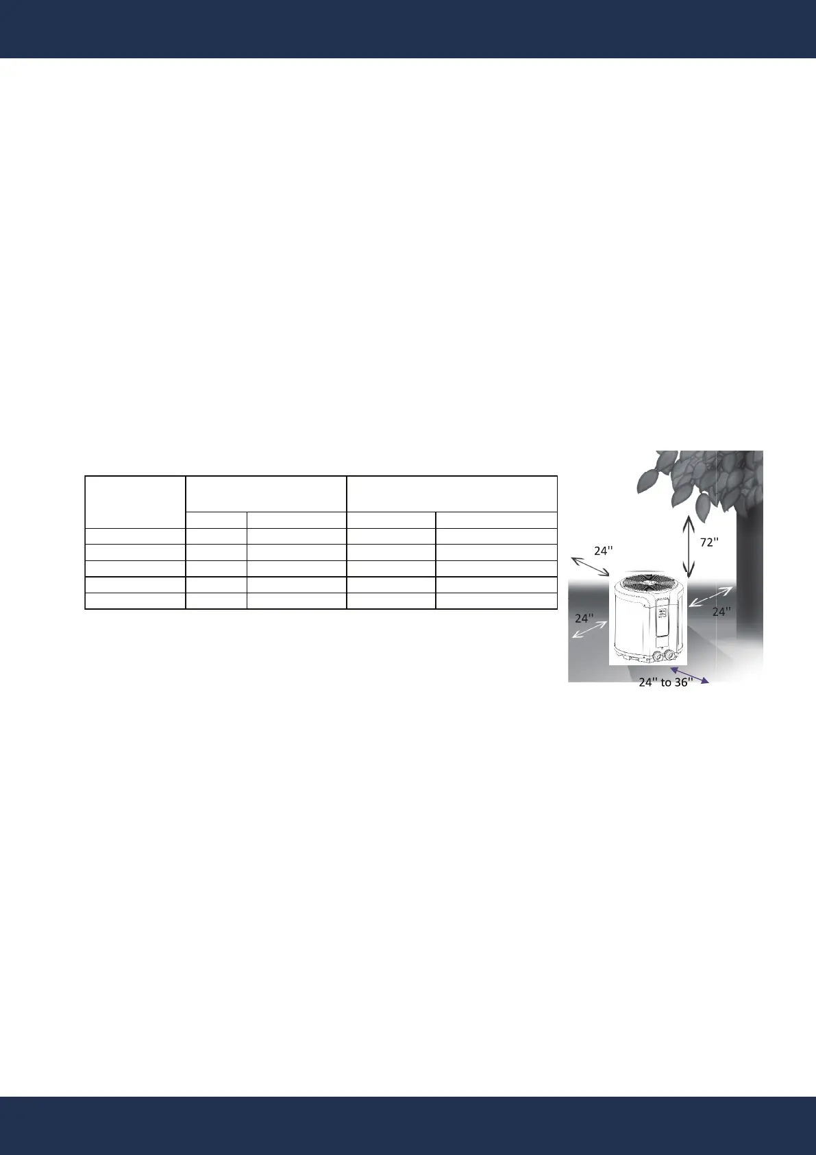
• Locate near the pool pump and filter to reduce water piping length, ensuring at least a 24"
clearance around the heat pump.
• Avoid excessive use of 90-degree bends in water piping. Install on a solid base, like con-
crete, ensuring isolation from building foundations to prevent noise transmission.
• Maintain a 72" clearance above for unobstructed air discharge and at least a 24" clearance
from walls or obstructions for intake and access.
INSTALLATION INSTRUCTIONS
Water Piping
• Follow this sequence: Pool -> Pool Pump -> Filter -> Heater -> Check Valve -> Chemical
Feeder -> Pool.
• Position automated chlorine systems downstream to protect equipment. Prefer rigid PVC
piping and ensure all joints are securely glued.
• After installation, check for leaks and verify no excessive pump head pressure is indicated
on the filter gauge.
• High-pressure flexible hoses are an option if they can withstand the pressure. A bypass is
unnecessary unless water flow exceeds 75 GPM.
• For installations with isolation valves, ensure water can circulate through the unit or be
drained when not in use to prevent corrosion from chlorine gas.
Wiring
• Wiring should be performed by a qualified electrician, following local codes. Use the correct
breaker and copper wire sizes as indicated on the heat pump label.
• Always power off the unit before accessing internal panels.
INCHES CENTIMETERS INCHES CENTIMETERS
RECOMMENDED CLEARANCES
FOR SERVICEABILITY
MINIMUM CLEARANCES
FOR OPERATION
OF HEAT
Installation Location and Clearance Requirements: