4 5
INSTALLATION
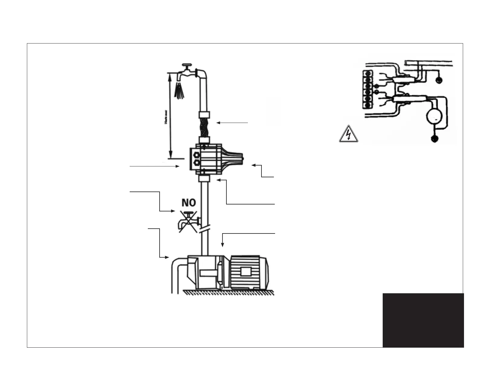
If the column of water between the
pump and the highest tap exceeds 15m
(static discharge head of 15m), the unit
cannot be installed directly on to the
pump. The unit has to be raised until the
column of water between the unit and
the highest tap does not exceed 15m. I.E.
if the column of water is 20m above the
pump, the unit must be placed 5m higher
than the pump, or have to use a 2.2 Bar
restarting/cut-in pressure device.
The unit is equipped with a check
valve to assist preventing the
pipeline from losing pressure.
PUMP PRESSURE
The MP PLUS is pre-set by the
manufacturer to have a restarting/cut in
pressure of either 1.5 to 2.0 Bar.
To use the MP PLUS the pressure
produced by the pump must be
at least 3 Bar.
Prior to operation, check unit and
pump are compatible.
Before starting the unit, check suction
and ensure that the pump is primed.
No taps or outlets can be installed
between the pump and the unit.
5
It is advisable to connect the units outlet to the
system by means of a fl exible hose.
Safety valve prevents water emission
in case of diaphragm breakage.
The unit is designed to be
installed directly on to the
pump, or between the pump
and the first tap.
Wiring diagram for connection
of single phase 220/240V
pumps up to 1.1 kW.
The product is not
weather-proof.
Do not install in direct
WIRING DIAGRAM
sunlight.
for MP and up to 1.5 kW for PC.
4
INSTALLATION INSTRUCTIONS
If the column of water between the
pump and the highest tap exceeds 15m
(static discharge head of 15m), the unit
cannot be installed directly on to the
pump. The unit has to be raised until the
column of water between the unit and
the highest tap does not exceed 15m.
I.E. if the column of water is 20m above
the pump, the unit must be placed 5m
higher than the pump, or have to use a
2.2 Bar rest
arting/cut-in pressure device.
The unit is equipped with a check
valve to assist p
reventing the
pipeline from losing pressure.
No taps or outlets can be
installed between the
pump and the unit.
PUMP PRESSURE
The PC is pre-set by the manufacturer to
have a restarting/cut in pressure of either
1.5 or 2.2 Bar, while the MP restarting/cut
in pressure is from 1.5 to 2.0 Bar.
To use the PC, the pressure produced by
the pump must be normally 0.8 Bar higher
than the pre-set pressure. To use the MP,
the pressure produced by the pump must
be at leas
t 3.5 B
ar.
Prior to operation check unit and pump
are compatible.
Before starting the unit check suction and
ensure that the pump is primed.
for MP and up to 1.5 kW for PC.
BROWN
BLUE
GREEN YELLOW
GREEN YELLOW
BLUE
BROWN
L1
N
U
V
PE
L1-1X220/240V
M
1
DANGER
RISK OF
ELECTRIC SHOCK
4
INSTALLATION INSTRUCTIONS
If the column of water between the
pump and the highest tap exceeds 15m
(static discharge head of 15m), the unit
cannot be installed directly on to the
pump. The unit has to be raised until the
column of water between the unit and
the highest tap does not exceed 15m.
I.E. if the column of water is 20m above
the pump, the unit must be placed 5m
higher than the pump, or have to use a
2.2 Bar rest
arting/cut-in pressure device.
It is advisable to connect the units outlet to the
system by means of a fl exible hose.
S
afety valve prevents water emission
in case of diaphragm breakage.
DO NOT TOUCH
It is imperative to install the unit
with the arrows in the upward
position.
The unit is designed to be
installed directly on to the
pump, or between the pump
and the first tap.
The unit is equipped with a check
valve to assist p
reventing the
pipeline from losing pressure.
No taps or outlets can be
installed between the
pump and the unit.
PUMP PRESSURE
The PC is pre-set by the manufacturer to
have a restarting/cut in pressure
of either
1.5 or 2.2 Bar, while the MP restarting/cut
in pressure is from 1.5 to 2.0 Bar.
To use the PC, the pressure produced by
the pump must be normally 0.8 Bar higher
than the pre-set pressure. To use the MP,
the pressure produced by the pump must
be at leas
t 3.5 Bar.
Prior to operation check unit and pump
are compatible.
Before starting the unit check suction and
ensure that the pump is primed.
Wiring diagram for connection
of single phase 220/240V
pumps up to 1.1 kW.
The product is not
weather-proof.
Do not install in direct
WIRING DIAGRAM
sunlight.
for MP and up to 1.5 kW for PC.
It is advisable to
connect the units
outlet to the system
by means of a
flexible hose.
Safety valve prevents
water emission in case
of diaphragm breakage.
It is imperative to install
the unit with the arrows
in the upward position.
The unit is designed
to be installed directly
on to the pump, or
between the pump and
the first tap.
DO NOT TOUCH
5
It is advisable to connect the units outlet to the
system by means of a flexible hose.
Safety valve prevents water emission
in case of diaphragm breakage.
The unit is designed to be
installed directly on to the
pump, or between the pump
and the first tap.
Wiring diagram for connection
of single phase 220/240V
pumps up to 1.1 kW.
The product is not
weather-proof.
Do not install in direct
WIRING DIAGRAM
sunlight.
for MP and up to 1.5 kW for PC.
4
INSTALLATION INSTRUCTIONS
If the column of water between the
pump and the highest tap exceeds 15m
(static discharge head of 15m), the unit
cannot be installed directly on to the
pump. The unit has to be raised until the
column of water between the unit and
the highest tap does not exceed 15m.
I.E. if the column of water is 20m above
the pump, the unit must be placed 5m
higher than the pump, or have to use a
2.2 Bar rest
arting/cut-in pressure device.
The unit is equipped with a check
valve to assist p
reventing the
pipeline from losing pressure.
No taps or outlets can be
installed between the
pump and the unit.
PUMP PRESSURE
The PC is pre-set by the manufacturer to
have a restarting/cut in pressure of either
1.5 or 2.2 Bar, while the MP restarting/cut
in pressure is f rom 1.5 to 2.0 Bar.
To use the PC, the pressure produced by
the pump must be normally 0.8 Bar higher
than the pre-set pressure. To use the MP,
the pressure produced by the pump must
be at leas
t 3.5 B
ar.
Prior to operation check unit and pump
are compatible.
Before starting the unit check suction and
ensure that the pump is primed.
for MP and u
BROWN
BLUE
GREEN YELLOW
GREEN YELLOW
BLUE
BROWN
L1
N
U
V
PE
L1-1X220/240V
M
1
DANGER
RISK OF
ELECTRIC SHOCK
4
INSTALLATION INSTRUCTIONS
If the column of water between the
pump and the highest tap exceeds 15m
(static discharge head of 15m), the unit
cannot be installed directly on to the
pump. The unit has to be raised until the
column of water between the unit and
the highest tap does not exceed 15m.
I.E. if the column of water is 20m above
the pump, the unit must be placed 5m
higher than the pump, or have to use a
2.2 Bar rest
arting/cut-in pressure device.
It is advisable to connect the units outlet to the
system by means of a flexible hose.
S
afety valve prevents water emission
in case of diaphragm breakage.
DO NOT TOUCH
It is imperative to install the unit
with the arrows in the upward
position.
The unit is designed to be
installed directly on to the
pump, or between the pump
and the first tap.
The unit is equipped with a check
valve to assist p
reventing the
pipeline from losing pressure.
No taps or outlets can be
installed between the
pump and the unit.
PUMP PRESSURE
The PC is pre-set by the manufacturer to
have a restarting/cut in pressure
of either
1.5 or 2.2 Bar, while the MP restarting/cut
in pressure is f rom 1.5 to 2.0 Bar.
To use the PC, the pressure produced by
the pump must be normally 0.8 Bar higher
than the pre-set pressure. To use the MP,
the pressure produced by the pump must
be at leas
t 3.5 Bar.
Prior to operation check unit and pump
are compatible.
Before starting the unit check suction and
ensure that the pump is primed.
Wiring diagram for connection
of single phase 220/240V
pumps up to 1.1 kW.
The productis not
weather-proof.
Do not install in direct
WIRING DIAGRAM
sunlight.
for MP and up to 1.5 kW for PC.
DANGER
RISK OF ELECTRIC SHOCK
This product is not
weatherproof.
Do not install in direct
sunlight.
Wiring Diagram
Wiring Diagram for connection
of single phase 220/240V pumps
up to 1.1 kW for MP PLUS
 Loading...