
C
Cheryl VasquezAug 7, 2025
What to do if Xylem Flygt FGC 400 Controller operation failed?
- OOscar LeeAug 7, 2025
If the Xylem Controller operation failed, retry the operation. If the problem persists, restart the controller.
What to do if Xylem Flygt FGC 400 Controller operation failed?
If the Xylem Controller operation failed, retry the operation. If the problem persists, restart the controller.
What to do if Xylem Flygt FGC 400 Controller failed to detect the USB drive?
If the Xylem Controller fails to detect the USB drive, remove the USB drive and then re-insert it.
What to do if Xylem Controller operation timed out?
If the Xylem Controller operation timed out, retry the operation. If the issue persists, restart the controller.
Why has the Xylem Flygt FGC 400 failed backing up configuration to USB drive?
The Xylem Controller may fail to back up the configuration to the USB drive because the USB drive is defective. To resolve this, remove the USB drive, re-insert it, or replace it with a new one.
What to do if Xylem Controller shows 'No configuration found on USB drive'?
If the Xylem Controller indicates that no configuration is found on the USB drive, remove the USB drive and check the USB drive.
Purpose of the manual, importance of reading before use, and where to keep it.
Explains safety messages, hazard levels, and symbols for hazard prevention.
Provides guidelines for handling and disposing of the product and its components responsibly.
Information on using spare parts, warranty terms, and customer support channels.
Instructions for inspecting packages and products upon delivery for damage or missing items.
Requirements for storing the product in a suitable environment to prevent damage.
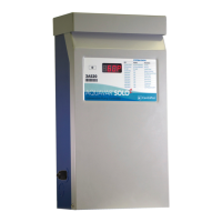
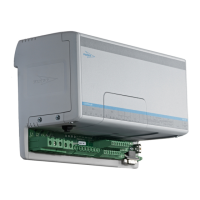
Describes the controller's design, applications, external interfaces, and expansion capabilities.
Lists product versions, article numbers, and descriptions.
Lists the certifications and approvals for the product (CE, UL, CSA).
Identifies key parts of the controller and their functions.
Explains the information found on the product's data plate.
Provides a high-level overview of the system components and their interactions.
Introduces the main functions of the controller.
Explains how levels are monitored using float switches or analog sensors.
Details how the pressure sensor measures hydrostatic pressure and converts it to water level.
Describes the Open Bell level sensor and its connection to the controller.
Explains float switches for level monitoring and their maximum count.
Details pump activation, runtime, dry run protection, and alternation modes.
Explains profile activation for different pumping behaviors based on time.
Describes the alarm function for monitoring station status and raising alerts.
Explains how running and history data are stored and accessed.
Warns against using the unit in environments with flammable or explosive gases/powders.
Provides step-by-step instructions for mounting the controller and HMI.
Emphasizes reading safety instructions before starting electrical work.
Lists requirements for electrical installation, including grounding and circuit breakers.
Specifies requirements for cable installation, condition, and bending radius.
Details the wiring for connecting a 3-phase pump motor to the internal contactor.
Explains how to connect a 3-phase pump motor using an external contactor.
Provides instructions and a table for connecting float switches to the controller.
Details how to connect passive or active 4-20 mA level sensors.
Explains how to connect pump sensor circuits to terminals T1 and T2.
Describes how to connect an external current transformer to the controller.
Provides instructions for connecting an external 24V alarm lamp.
Explains how to connect an external switch for alarm silencing or reset.
Details the connection of an external hand-off-auto switch for pump control.
Provides wiring details for connecting the HMI to the controller.
Explains how to connect communication devices via RS-232 or modem.
Details wiring for connecting an external device to the general-purpose digital output.
Explains how to connect an external switch to the general-purpose digital input.
Provides wiring instructions for connecting a 3-phase power supply.
Details wiring for connecting a single-phase power supply.
Identifies and describes the components and buttons of the HMI user interface.
Guides through the initial setup and commissioning of the controller.
Explains how to use the setup wizard for initial configuration.
Outlines common procedures for operating and configuring the controller.
Describes how to adjust pump start and stop levels using analog sensors.
Details configuring the general-purpose digital input for various functions.
Explains how to select and change the active pumping profile.
Guides on setting the correct date and time for the controller.
Describes how to enable or disable various controller functions.
Explains how to configure the Minimize Fat Build-Up function.
Details how to adjust alarm parameters like activation and deactivation delays.
Guides on configuring motor protection parameters like full load current.
Explains how to configure the Power On Delay function.
Provides a table of common alarms and their probable causes for troubleshooting.
Lists controller-specific alarms like Comms Fail and Startup Failure.
Recommends basic preventive maintenance practices for the unit.
Details the procedure for upgrading the controller's firmware using a USB drive.
Explains how to upgrade the HMI firmware using a USB drive.
Guides on backing up controller configuration settings to a USB drive.
Details how to restore controller configuration settings from a USB drive.
Lists controller messages and alarms with remedies and probable causes.
Provides steps to troubleshoot level sensor issues and check settings.
Outlines a procedure for checking HMI faults, particularly for Comms Fail alarms.
Describes the Home menu, showing pumps and well, and access to settings.
Details the information displayed for pumps in the Home menu.
Explains the information displayed for the well in the Home menu.
Shows the Home menu screen and its navigation options.
Describes the Alarms menu, listing active alarms and their status.
Explains the History menu for viewing stored alarm data and statistics.
Covers settings for Language, Pump Control, Motor Protection, and Alarms.
Details settings for level devices, delays, runtime, and alternation modes.
Details GP Input Usage, Level Units, Sensor Range, and Profile settings.
Explains settings for Power On Delay, Minimize Fat Build-Up, and Maintenance Run.
Details settings for motor protection, including phase mode, voltage, and pump parameters.
Details alarm types, parameters, and extra alarm parameters for customization.
Covers communication protocols, channel types, and addresses.
Covers site name, date/time settings, and HMI configuration.
Details settings for the HMI screen, including buzzer and backlight.
Covers functions for backing up and restoring configuration settings via USB.
Provides read-only access to status of digital inputs, analog inputs, and outputs.
Details specific analog input terminals like FLS, Bell Pressure, and UPS voltage.
Provides voltage and phase angle readings for power supply phases.
Displays current readings for pump phases and phase angles.
Details the status of digital outputs for pump control and indicators.
Provides controller system information like voltage, current, and temperature.
Details parameters within the Setup Wizard for language, pumps, sensors, and more.
Provides information on serial numbers and firmware versions for HMI and controller.
Details controller and HMI reset procedures, including factory reset.
Provides physical dimensions of the controller unit.
Details operating/storage conditions, humidity, and altitude limits.
Specifies the IP rating and lists electrical data like supply voltage and frequency.
Provides a detailed breakdown of controller terminals and their connections by section.
Details connections for power supply (L1, L2, L3, N) and protective earth.
Describes terminals for external contactors, start capacitors, and digital outputs.
Details terminals for analog sensors, float switches, and digital inputs.
Covers RS-232, USB, RS-485, and HMI CAN bus connections.
Provides licensing information for the U8glib graphics library.
| Type | Controller |
|---|---|
| Manufacturer | Xylem |
| Model | Flygt FGC 400 |
| Operating temperature | -20°C to +60°C |
| Inputs | Analog and digital inputs |
| Outputs | Analog and digital outputs |
| Communication | Modbus RTU |