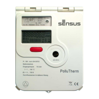
Heat / Cooling meter integrator PolluTherm
Installation and operation instructions
M H 6111 INT PolluTherm, page 1
The integrator PolluTherm is used for energy
consumption measurement in heating or cooling
systems filled with the energy carrier liquid water.
PolluTherm may also be used with water
containing antifreeze using a programmed
correction factor. In this case the PolluTherm is
not officially metrologically calibrated. These
installation and operation instructions specify how
to install and operate the integrator PolluTherm.
They are an essential part of the supplied items
and shall be handed over to the final user.
Content
Supplied items ..................................................... 1
1. Technical data ................................................. 1
2. Safety instructions ........................................... 2
3. Required tools .................................................. 2
4. Combination of the sub-units ........................... 2
4.1 Programming the input pulse value ............ 2
5. Installation of the sub-units .............................. 3
5.1 Flow sensor ................................................ 3
5.3 Mounting of the integrator ........................... 4
6. Connection of the sub-units ............................. 4
6.1 Connection of the flow sensor .................... 5
6.2 Connection of the temperature sensors ...... 5
7. Exchange of the integrator module .................. 5
8. Display options ................................................ 6
8.1 User menu (example) ................................. 6
8.2 Target day menu (example) ....................... 7
8.3 Archive menu (example)............................. 7
8.4. Service menu (example) ............................ 8
8.5 Control menu for tariff purposes (example) 9
8.6 Parameter menu (example) ........................ 9
9. Functional test, sealing .................................. 10
10. Potential error situations .............................. 10
11. Data interface and options ........................... 10
11.1 Optical interface ..................................... 10
11.2 M-Bus-plug-in unit acc. to EN 13757-3 ... 10
11.3 Remote reading plug-in unit ................... 11
11.4 M-Bus plug-in unit with two contact inputs
....................................................................... 11
11.5 USB plug-in unit (for M-Bus slot) ............ 11
11.6 LONWORKS
®
-FTT10A (for M-Bus slot) . 11
11.7 Inserting the plug-in unit into the heat
meter .............................................................. 11
11.8 Combined heating/cooling meter (ordering
option) ............................................................ 11
11.9 Optional integrated data logger (ordering
option) ............................................................ 12
11.10 Retrofitting from battery unit to power
supply unit ...................................................... 12
12. Information on the extension of temperature
sensor cables ................................ ..................... 12
Annex 1: Declaration of conformity acc. directive
2004/22EC (MID) ............................................... 14
Supplied items
Integrator PolluTherm (incl. temperature
sensors and immersion sleeves, where
appropriate)
Sealing material (self-lock seals, sealing
wire), cable binders for strain relief
Fastening material (2 screws,
2 dowels, C-rail)
These installation and operating instructions
1. Technical data
Integrator
Temperature measuring
range
= 1 … 180 °C
Temperature difference
range
∆ = 3 … 150 K
Switch-off threshold 0,15 K
Measuring accuracy
Better than (%):
+ (0,5 + ∆
min
/ ∆)
Updating time and
integration cycles resp.:
- Temperatures
- Flow rate, power
- Energy, volume
2 sec
4 sec
4 sec (16 sec *)
* in case of battery supply
Optical data interface
Physical acc. to EN 61107
Data record acc. to EN 13757-3
Suitable temperature
sensors
Pt 500
Connection in two- or four-wire
technology
Power supply
(certification period of the
meter may be defined by
national laws)
Battery for 6 years
(optional: 11 years)
or mains supply 230 V AC or
24 V AC
Electromagnetic
environment condition
Class E 1
Mechanical environment
condition
Class M 2
Protection class IP 54
Ambient temperature 5 … 55 °C
Storing temperature -20 … +65 °C
Relative air humidity < 93 %
Size (H x B x T)
in terms of wall mounting
ca. 159 x 125 x 52 mm
Pulse input value
in l
0,25
or
1
2,5
or
10
25
or
100
250,
1.000 or
10.000
Display of the
integrator with
decimal digits for
m³, MWh or GJ
00000,000 000000,00 0000000,0 00000000
Pulse value in case
of remote heat
quantity reading in
MWh or GJ
0,001 0,01 0,1 1
Pulse value in case
of remote volume
reading in l
1 10 100 1.000