Do you have a question about the Yaesu FTR-710A and is the answer not in the manual?
Detailed specifications for transmitter RF power, frequency, modulation, and audio characteristics.
Detailed specifications for receiver sensitivity, stability, selectivity, and intermodulation.
Specifications for the FTR-2410A duplexer including frequency range, separation, and insertion loss.
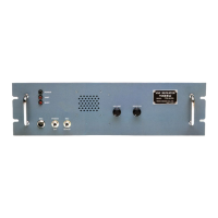
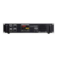
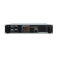
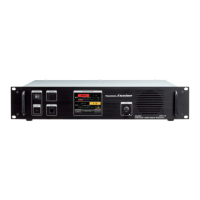
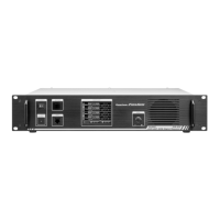
Description of the power switch, power LED, XMIT LED, and BUSY LED.
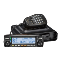
Description of MIC/REPEAT switch, MIC jack, and volume control.
Description of the squelch control operation for the repeater.
Description of TX (OUT), RX (IN), AC, and DC Terminal Posts.
Description of FUSE, ACC-1, ACC-2, DTMF Switch, and SP connectors.
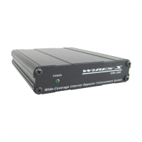
Guidance on antenna placement, DC power supply backup, and equipment location.
Information on selecting the correct AC power supply voltage based on the unit.
Instructions for operating the repeater and setting front panel controls.
Explanation of special functions like Time Out Timer and Hang Up Delay Timer.
Procedure for installing the FTS-32R Tone Squelch Unit.
Procedure for installing the FTS-5 Tone Burst Decoder Unit.
Schematic diagram for the FTS-32R Tone Squelch Unit.
Schematic diagram for the FTS-5 Tone Burst Decoder Unit.
Block diagram showing frequency relationships for the FTR-710A model.
Block diagram showing frequency relationships for the FTR-2410A model.
Block diagram showing frequency relationships for the FTR-5410 model.
Description of the receiver unit's circuit operation.
Description of the Carrier Operated Relay (COR) unit's circuit.
Component placement diagrams for top and bottom views of the unit.
Procedures for aligning the receiver sections of FTR-710A, FTR-2410A, and FTR-5410 models.
Procedures for aligning the transmitter sections of FTR-710A, FTR-2410A, and FTR-5410 models.
Alignment procedures for Power Supply, COR, DTMF, Duplexer, and FL-2450 amplifier.
Adjusting Time Out and Hang Up timers using DIP switches and potentiometers.